Methods of increasing fracture resistance in low permeability formations

a low permeability, fracture resistance technology, applied in the direction of fluid removal, sealing/packing, borehole/well accessories, etc., can solve the problems of fracture and thus induced mud loss of formation, difficult situation, and near impossible drilling of certain depleted zones, etc., to increase the fracture resistance of a low permeability formation

Active Publication Date: 2010-11-11
BP CORP NORTH AMERICA INC +2
View PDF18 Cites 29 Cited by
  • Summary
  • Abstract
  • Description
  • Claims
  • Application Information

AI Technical Summary

Benefits of technology

[0009]In one aspect, embodiments disclosed herein relate to a method of increasing the fracture resistance of a low permeability formation that includes emplacing a wellbore fluid in a wellbore through the low permeability formation, the wellbore fluid comprising: a settable carrier fluid; and a solid particulate bridging material; increasing the pressure in the wellbore such that fractures are formed in the formation; allowing the settable carrier fluid to enter the fractures; bridging and sealing the mouths of the fractures to form a substantially impermeable bridge proximate to the mouth of the fractures thereby strengthening the formation; and holding the increased pressure for an amount of time sufficient for setting of the carrier fluid in the fractures.
[0010]In another aspect, embodiments disclosed herein relate to a method of drilling a wellbore through a low permeability formation that includes drilling the wellbore while circulating a first wellbore fluid into the wellbore; emplacing a wellbore fluid in a wellbore through the low permeability formation, the wellbore fluid comprising: a settable carrier fluid; and a solid particulate bridging material; increasing the pressure in the wellbore such that fractures are formed in the formation; allowing the settable carrier fluid to enter the fractures; bridging and sealing the mouths of the fractures to form a substantially impermeable bridge proximate the mouth of the fractures thereby strengthening the formation; and holding the increased pressure for an amount of time sufficient for setting of the carrier fluid in the fractures.
[0011]In yet another aspect, embodiments disclosed herein relate to a method of increasing the fracture resistance of a low permeability formation that includes emplacing a wellbore fluid in a wellbore through the low permeability formation, the wellbore fluid comprising: a settable carrier fluid comprising an oleaginous base fluid, an epoxidized natural oil, and at least one crosslinking agent; a solid particulate bridging material; and a bridge sealing material; increasing the pressure in the wellbore to above an initial or re-opening fracture pressure of the formation such that fractures are induced in the formation; allowing the settable carrier fluid to enter the fractures, the solid particulate bridging material to prop open the fractures, and the bridge sealing material to form a substantially fluid impermeable bridge proximate the mouths of the fractures, thereby strengthening the formation and preventing the fractures from further growth in length; and holding the increased pressure for an amount of time sufficient for setting of the carrier fluid in the fractures.
[0012]In yet another aspect, embodiments disclosed herein relate to a method of increasing the fracture resistance of a low permeability formation that includes emplacing a wellbore fluid in a wellbore through the low permeability formation, the wellbore fluid comprising: a settable carrier fluid comprising water and a cementious material; a solid particulate bridging material; and a bridge sealing material; increasing the pressure in the wellbore to above an initial or re-opening fracture pressure of the formation such that fractures are induced in the formation; allowing the settable carrier fluid to enter the fractures, the solid particulate bridging material to prop open the fractures, and the bridge sealing material to form a substantially fluid impermeable bridge proximate the mouths of the fractures, thereby strengthening the formation and preventing the fractures from further growth in length; and holding the increased pressure for an amount of time sufficient for setting of the carrier fluid in the fractures.

Problems solved by technology

While it is highly advantageous to maintain the wellbore pressures above the pore pressure, on the other hand, if the pressure exerted by the wellbore fluids exceeds the fracture resistance of the formation, a formation fracture and thus induced mud losses may occur.
Therefore, a major constraint on well design and selection of drilling fluids is the balance between varying pore pressures and formation fracture pressures or fracture gradients though the depth of the well.
A particularly challenging situation arises in depleted reservoirs, in which pressure depleted formations are neighbored by or inter-bedded with normally or abnormally pressured zones.
This can make the drilling of certain depleted zones nearly impossible because the mud weight required to support the shale exceeds the fracture resistance of the pressure depleted sands and silts.

Method used


Image

  • Methods of increasing fracture resistance in low permeability formations
  • Methods of increasing fracture resistance in low permeability formations
  • Methods of increasing fracture resistance in low permeability formations

Examples


example 1

Formulation

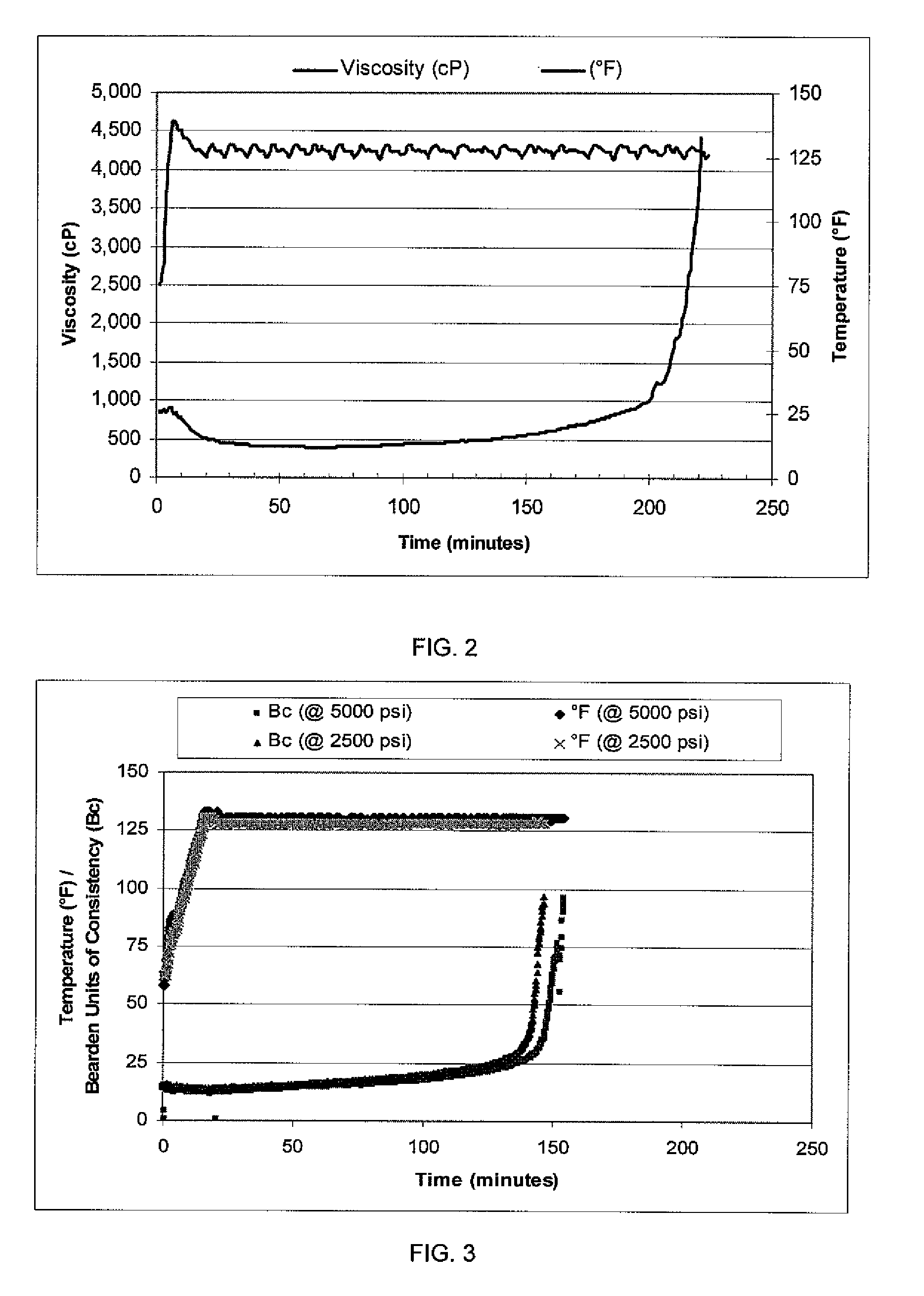
[0052]The following example includes an oil-based pill and experimental data showing properties of the set fluid. The pill was formed, using a Hamilton Beach mixer, by mixing and shearing the required quantity of diesel (low sulfur No. 2) and EMI-1160, an epoxy resin available from M-I LLC (Houston, Tex.), for five minutes; adding VG-SUPREMET™, an organoclay viscosifier available from M-I LLC (Houston, Tex.) and shearing until homogenous. The SAFE-CARB® solids, calcium carbonate available from M-I LLC (Houston, Tex.), are then mixed in until homogenous. Prior to use, EMI-1161, a polyamine and EMI-1162, an amine blend, both available from M-I LLC. (Houston, Tex.), are mixed in until homogenous. The pill components are listed in Table 1 below.

TABLE 1ComponentQuantityDiesel oil0.137 bbl / lbblVG-SUPREME ™3.50 ppbEMI-11600.43 bbl / lbblSAFE-CARB ® 40105.60 ppbSAFE-CARB ® 25020.00 ppbSAFE-CARB ® 50025.00 ppbG-SEAL ®25.00 ppbEMI-116176 ppbEMI-11627.4 ppb

[0053]Temperature and Pressu...

example 2

[0075]In another example, casing was set at 2388 feet. The shoe was drilled out and tested to demonstrate a native formation strength of 988 psi above mud hydrostatic or 17.32 ppg. The well was drilled to expose 90 feet of shale formation and the leak-off test was re-run to confirm a native strength of 17.04 ppg.

[0076]A cement pill was placed across the entire open hole with a stress cage formulation containing 25 lbs / bbl BARACARB® 600, ground marble, 5 lbs / bbl BARACARB® 150 and 10 lbs / bbl STEEL-SEAL® regular, industrial carbon, all of which are available from Baroid Fluid Services (Houston, Tex.). Water content in the cement was adjusted to produce a 1000 psi compressive strength at the time the hole was redrilled. The cement / stress cage pill was squeezed into place and pressure held while the cement set. The hole was re-drilled (all but the last 10 feet). A leak-off was run to a pressure of 1179 psi above mud hydrostatic or 18.58 ppg. 18.58 ppg was the anticipated overburden at th...


PUM


Abstract

A method of increasing the fracture resistance of a low permeability formation that includes emplacing a wellbore fluid in a wellbore through the low permeability formation, the wellbore fluid comprising: a settable carrier fluid; and a solid particulate bridging material; increasing the pressure in the wellbore such that fractures are formed in the formation; allowing the settable carrier fluid to enter the fractures; bridging and sealing the mouths of the fractures to form a substantially impermeable bridge proximate the mouth of the fractures thereby strengthening the formation; and holding the increased pressure for an amount of time sufficient for setting of the carrier fluid in the fractures is disclosed.

Description

BACKGROUND OF INVENTION[0001]1. Field of the Invention[0002]Embodiments disclosed herein relate generally to methods of increasing the fracture resistance of low permeability formations.[0003]2. Background Art[0004]During the drilling of a wellbore, various fluids are typically used in the well for a variety of functions. The fluids may be circulated through a drill pipe and drill bit into the wellbore, and then may subsequently flow upward through wellbore to the surface. Common uses for well fluids include: lubrication and cooling of drill bit cutting surfaces while drilling generally or drilling-in (i.e., drilling in a targeted petroliferous formation), transportation of “cuttings” (pieces of formation dislodged by the cutting action of the teeth on a drill bit) to the surface, controlling formation fluid pressure to prevent blowouts, maintaining well stability, suspending solids in the well, minimizing fluid loss into and stabilizing the formation through which the well is being...

Claims


Application Information

Patent Timeline
IPC IPC(8): E21B43/26
CPCE21B43/26E21B33/138
Inventor ALBERTY, MARK WILLIAMASTON, MARKFRIEDHEIM, JIMSANDERS, MARKSANT, RANDALL
Owner BP CORP NORTH AMERICA INC
Why Eureka
Try Eureka