
Non load-bearing metal wall stud having increased strength

a technology of wall studs and metal plates, which is applied in the direction of girders, joists, trusses, etc., can solve the problems of increasing the difficulty of installing self-taping screws that are commonly used to attach wall boards to the studs, reducing the thickness of other materials, and reducing the strength of known structural components, so as to overcome or ameliorate the disadvantages of known structural members, increase the deflection resistance, and improve the effect of strength

Active Publication Date: 2010-11-11
SUPER STUD BUILDING PRODS
View PDF39 Cites 31 Cited by
  • Summary
  • Abstract
  • Description
  • Claims
  • Application Information

AI Technical Summary

Benefits of technology

[0010]It is an object of the present invention to provide a metal wall stud having a substantially uniform material gauge, which substantially overcomes or ameliorates disadvantages of known structural members.
[0011]It is an object of the present invention to provide a metal wall stud having an increased strength, in particular, increased deflection resistance, without the necessity of increasing the thickness or tensile strength thereof.
[0012]It is also an object of the present invention to provide a non load-bearing metal wall stud that can be made with reduced sheet metal wall thickness while providing increased strength by including in the sheet metal body of the stud a skirt that is bent inwardly from the flange lip at a non-right angle and, optionally, a pattern of knurled parallel channels in the flange and, further optionally, in an central area of the web as well.
[0024]In these embodiments, the free edge of the flange elements have a lip having extending therealong, for added stiffness.
[0025]In these embodiments, the lips have a free edge thereon and skirts extending along the free edges of the lips, for yet further added stiffness.

Problems solved by technology

Others have a reduced thickness, but do not provide adequate support.
Some manufactures increase the Ksi (thousand pound per square inch of tensile strength) of the steel to increase the ability of the stud to achieve greater heights, but using a higher Ksi steel, for example 50 Ksi, makes the installation of self taping screws that are commonly used to attach wall board to the studs, more difficult.

Method used


Image

  • Non load-bearing metal wall stud having increased strength
  • Non load-bearing metal wall stud having increased strength
  • Non load-bearing metal wall stud having increased strength

Examples


Embodiment Construction

[0036]The invention provides sheet metal studs, suitable for use in erecting various structures such as internal partition walls and the like.

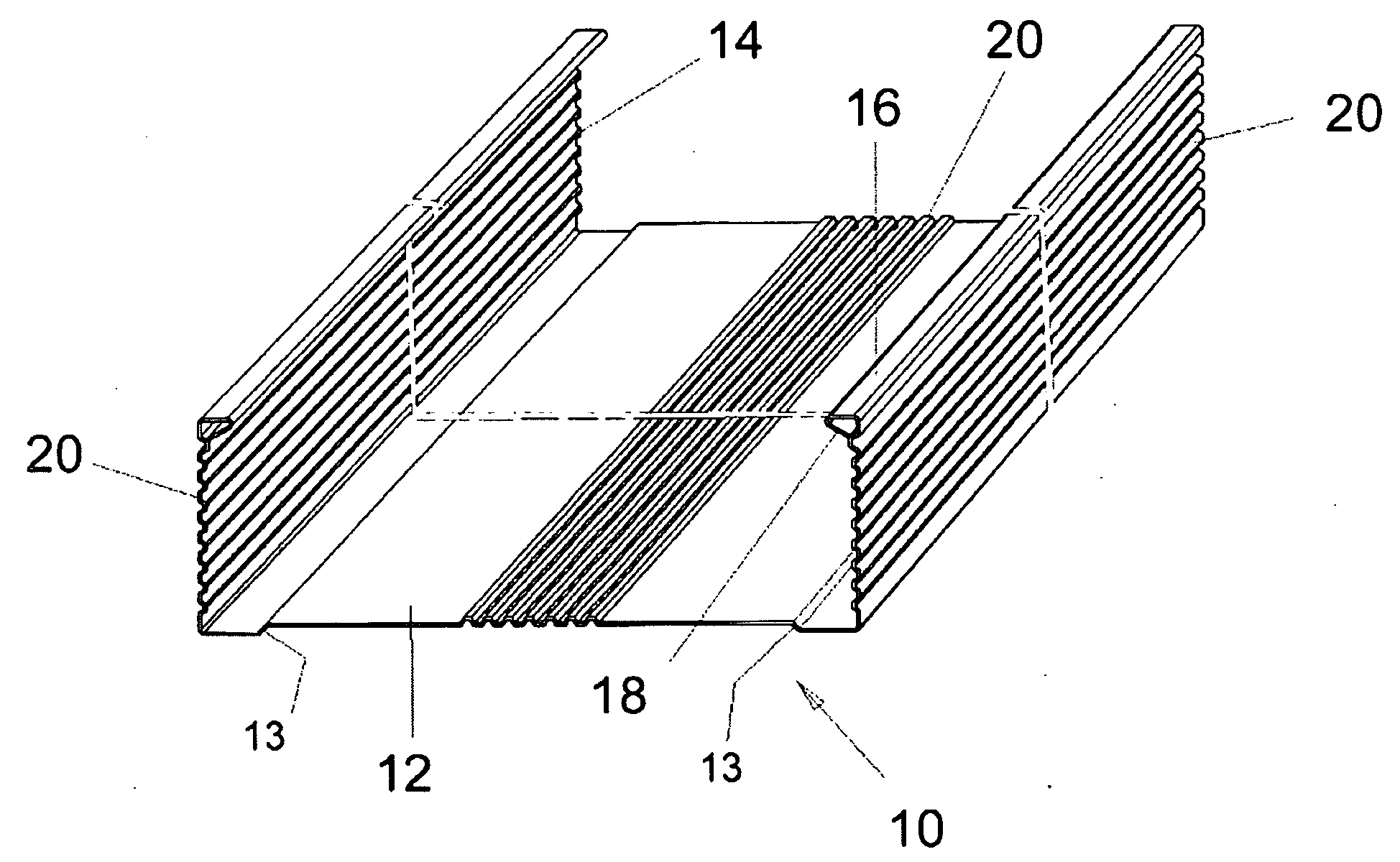
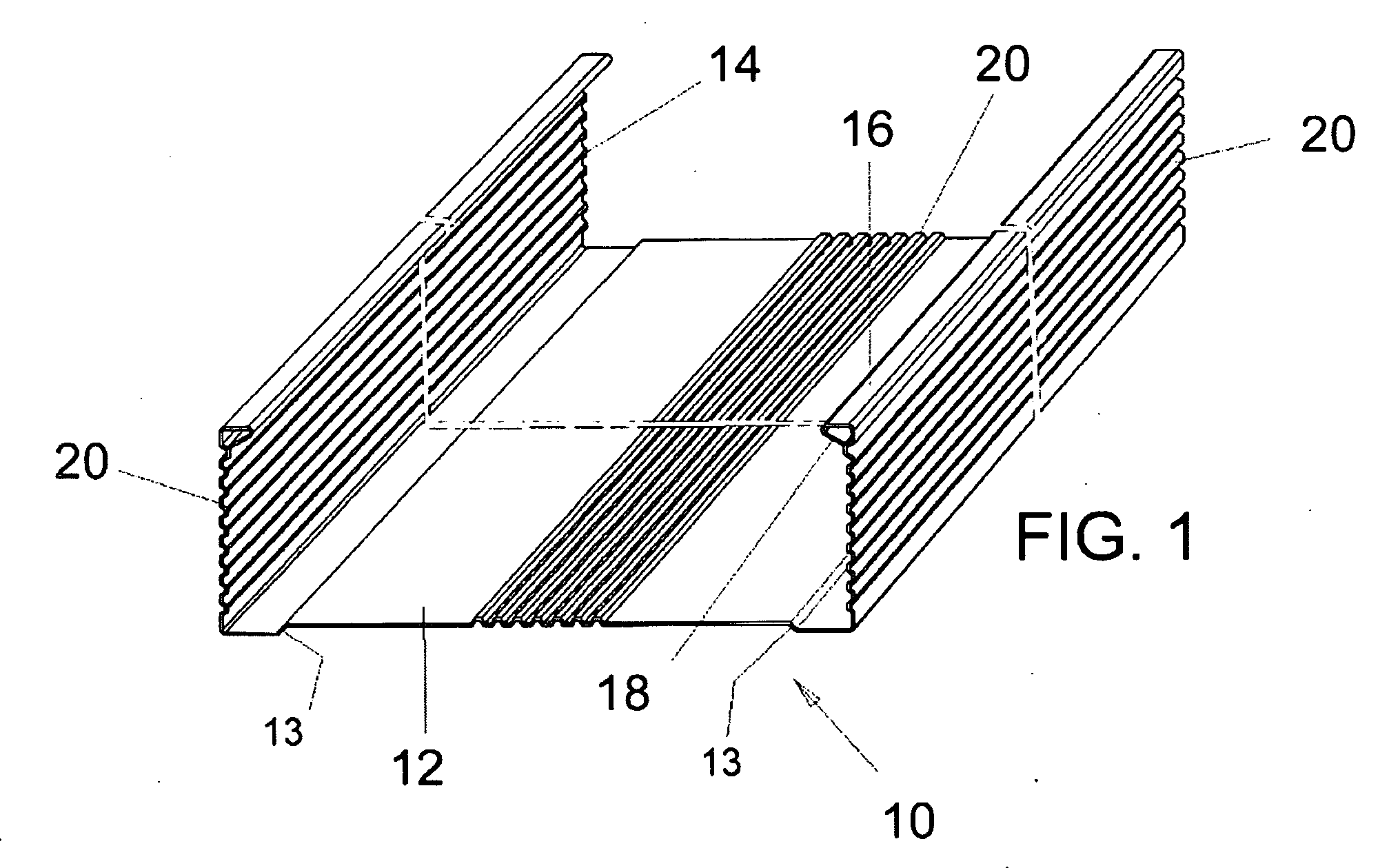
[0037]Referring now to FIG. 1, a preferred embodiment of the invention there illustrated comprises a metal stud generally designated 10, which is formed of sheet metal, preferable galvanize or otherwise anti-corrosion treated steel. The steel of the present invention can be selected to have a tensile strength of about 33 to 45 Ksi (thousand pounds per square inch) so that installation using self taping screws is expedited.

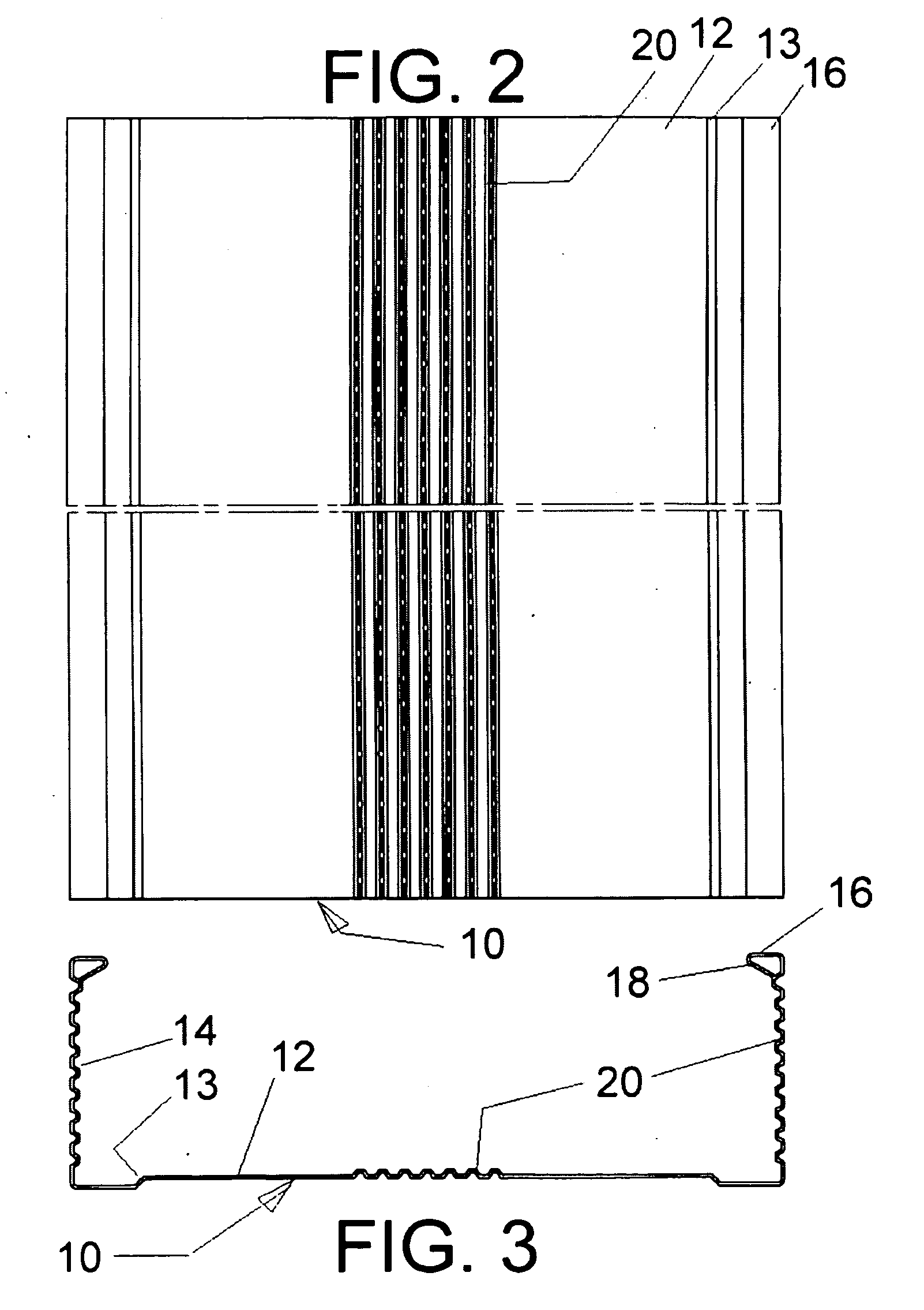
[0038]The stud 10 is formed of an initially flat sheet of metal that is bent into shape by known forming equipment. The stud 10 is thus formed to include a web 12 which is essentially planar, and edge flanges 14 along each side edge of the web 12. Each of the flanges 14 is formed by bending the sheet metal at opposite side edges of the web 12, at right angles. Lips 16 are formed on the outer edge of each flange 14, again by b...


PUM


Abstract

A non load-bearing metal wall stud has a sheet metal body with a web, a pair of flanges extending at right angles to the web, a pair of lips, each extending at a right angle from a straight edge of one of the flanges and a pair of skirts each extending at an angle from the straight edge of one of the lips. Knurled channels in the flanges and in the web stiffen the stud further.

Description

FIELD AND BACKGROUND OF THE INVENTION[0001]The present invention relates generally to the field of metal building components and, in particular, to a new and useful metal wall stud.[0002]Buildings have long been constructed of structural framing systems. Wood has long been the material of choice for the components of these systems. In recent times, however, steel and other metal structural components have been created to replace the wood framing components in most commercial and some residential construction. Thus, the erecting of interior partitions within buildings to divide the interior space into smaller sections or areas is commonly completed by erecting a framework of metal studs.[0003]The inventor of the subject application has invented or co-invented various improvements in the field including U.S. Pat. No. 7,478,505 for Metal Stud Arrangement; U.S. Pat. No. 7,383,665 for Header Arrangement; U.S. Pat. No. 7,356,970 for Metal Building Construction; U.S. Pat. No. 6,964,140 for...

Claims


Application Information

Patent Timeline
IPC IPC(8): E04C3/04
CPCE04C3/09E04C3/32E04C2003/0473E04C2003/0434E04C2003/046E04C2003/0421
Inventor FROBOSILO, RAYMOND C.
Owner SUPER STUD BUILDING PRODS
Learn More