Method and apparatus for warming or cooling a fluid

a fluid and apparatus technology, applied in the field of methods and apparatus for warming or cooling fluids, can solve the problems of inability of current fluid warmers lack of sensitivity and fine control in regulation, and inability to achieve optimal performance at low flow rate, etc., to achieve precise control, reduce manufacturing costs, eliminate or limit damage to fluid and/or patient

Inactive Publication Date: 2010-11-04
ROSIELLO KEITH MICHAEL
View PDF30 Cites 13 Cited by
  • Summary
  • Abstract
  • Description
  • Claims
  • Application Information

AI Technical Summary

Benefits of technology

[0011]The invention described herein overcomes the aforementioned limitations by integrating the IV set with a novel warming method and apparatus, for example. In one embodiment of the present invention, the novel method and apparatus may use a variety of power sources from AC to a small battery of both rechargeable and disposable types. The method and apparatus may also include a single delivery-line unit (disposable unit) between the fluid supply bag and the patient connection to warm the fluid along its entire length by integrating the fluid delivery tube with a heat source. The method and apparatus may also include a controller (reusable unit), which contains and executes control / feedback logic program with unique heat balance algorithm that provides a precise level of control, in a full range of transfusion environments, on the amount of heat applied to the fluid. The method and apparatus may also include a single delivery-line component with minimal manufacturing cost.
[0012]Accordingly, this novel design according to some embodiments of the present invention may allow the fluid delivery pathway to be flexible, non-kinking, in lengths of 1 foot and greater. The choice of power sources, heat balance algorithm, and the ability of the fluid warmer to act as an IV set enables some of the embodiments of the present invention well suited to portability and use in a variety of environments. Gradual and efficient warming over the entire non-serpentine fluid delivery length, for example, may support low and high (1 mL / min to 600 mL / min) flow rates for a variety of parenteral fluids, including whole blood, substantially eliminating or limiting damage to the fluid and / or patient, or overheating.
[0013]Thus, the new design according to some embodiments of the present invention may provide a fluid warmer that is portable, adaptable to different environments and easy to use.
[0014]Accordingly, in one embodiment of the present invention, a method of heating a fluid for delivery into the body of a patient may include providing a low cost fluid delivery tube having a first end for connection to a fluid source and a second end for delivering the fluid from the fluid source to a destination. The method may also include applying an electrical current to a heating element proximate to and / or within the fluid delivery tube to heat fluid therein to a predetermined temperature, sensing, via multiple thermal sensor positioned on the fluid delivery tube and in the fluid pathway, fluid temperatures. Then, the fluid temperature values are used by the heat balance algorithm to adjust the current applied to heating element, which regulates the amount of heat applied to the fluid.

Problems solved by technology

Yet other parenteral fluids are cryo-preserved and, due to time constraints, often only uniformly thawed just enough to allow fluid flow.
The methods and apparatus available to suitably warm fluids have several limitations in common.
The primary limitation shared by a majority of current fluid warmers, or blood warmers, as they are sometimes known, is an inability to achieve the target fluid temperature at low flow rates, which results from the need to protect the fluid from overheating.
The inability of these current fluid warmers to achieve optimal performance at low flow rate is due to the lack of sensitivity and fine control in the regulation of the heat supplied to the fluid.
Inefficient application of heat to the fluid and extended, serpentine flow paths between fluid supply and patient negatively effect the response-time of many fluid warmers, hence a large safety factor is required at low flow rates to reduce the probability of overheating the fluid.
Another limitation of current fluid warmers is the lack of flexibility with respect to flow rate range, fluid temperature output and physical specification, due to the singular focus of these methods and apparatus on fluid warming in a surgical environment.
Current fluid warmers do not posses the sensitivity and rapid response-time required for optimal performance in emergent applications, such as ambulances, emergency rooms and field use.
For example, the use of higher flow rates and the occurrences drastic flow rate changes are rarely encounter in surgical situations, but may often be necessary in emergent situation.
The inefficient heat-application methods used by current fluid warmers dramatically increase the response-time, which results in a failure to reach the target fluid temperature a high flow rates.
Similarly, the extended flow path and lack of sensitivity in current fluid warmers results in fluid overheating during a drastic flow rate reduction, which is rare event in a surgical environment.
The post-warmer IV set is a source of significant heat loss, creating a varying temperature differential between the fluid warmer and the patient.
Furthermore, the need for IV sets is not preferred for portability and field use.
The majority of the daily operating costs of current warmers are attributed to the cost of the disposable unit.
However, the cost of the disposable unit for current fluid warmers can be high, due to the inclusion of multiple high-value components and the use complex manufacturing processes.

Method used


Image

  • Method and apparatus for warming or cooling a fluid
  • Method and apparatus for warming or cooling a fluid
  • Method and apparatus for warming or cooling a fluid

Examples


Embodiment Construction

[0044]A description of preferred embodiments of the invention follows.

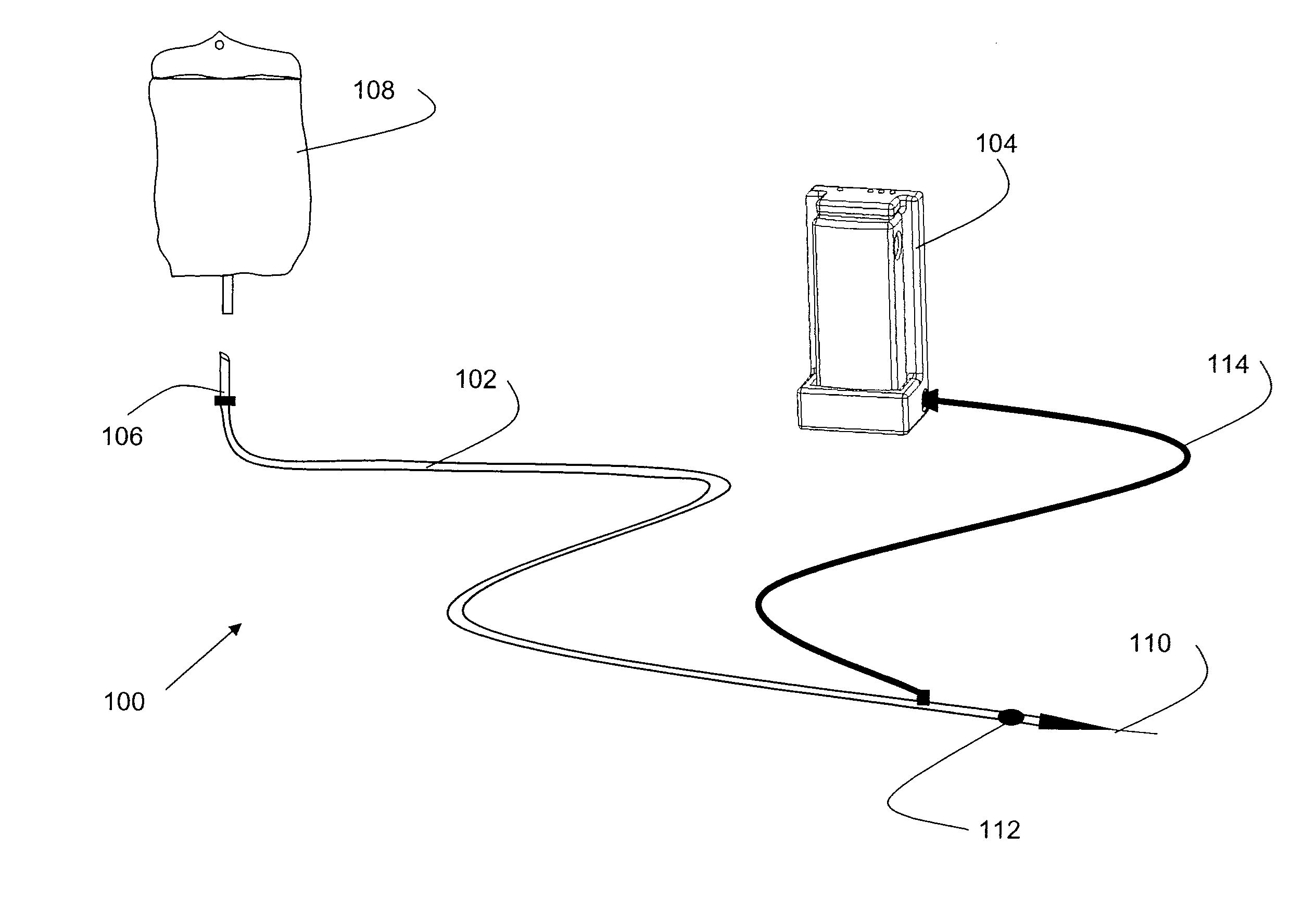
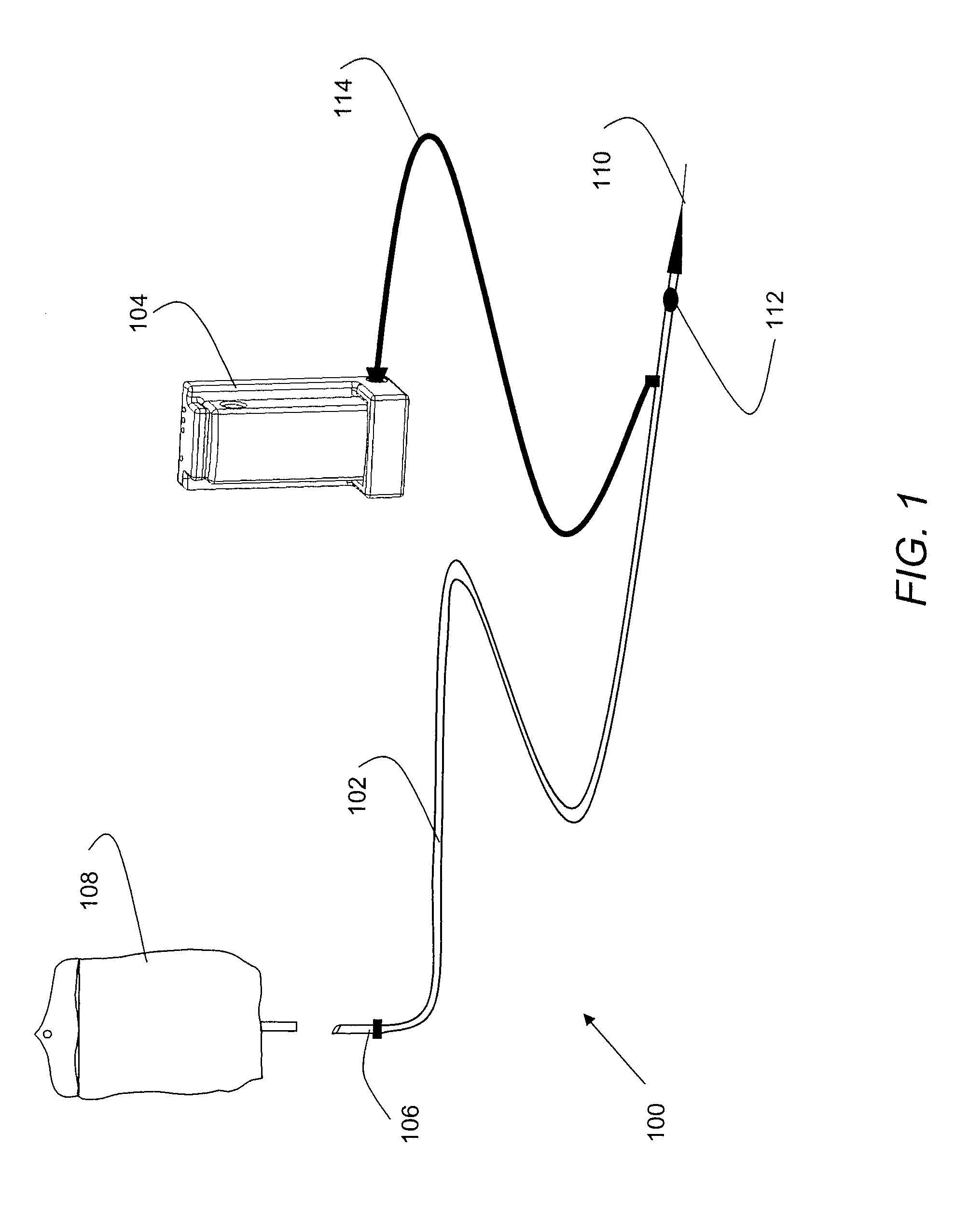
[0045]As shown in FIG. 1, some of the embodiments of the present invention include the following features. A fluid warming system 100 may include a fluid delivery line 102 and a controller 104. The system may further include a lead tube 106, comprised of standard medical grade tubing, one end of which is attached and sealed to the control end of the fluid delivery line, using commonly know techniques such as solvent bonding or barbed tube fittings. A luer lock 108 may be connected to the other end of the lead tube, and may be used to fluidly connect the fluid delivery line to a container 112 (e.g., bag) of fluid for delivery to the body of a patient. Such luer locks may include those disclosed in U.S. Pat. Nos. 5,620,427, 5,738,144 and 6,083,194, each of which is herein incorporated by reference. Each of the luer locks is preferably attached to the fluid delivery line and forms a sterile and / or airtight seal there...


PUM


Abstract

A method and system for heating or cooling a fluid to be delivered into the body of a patient is provided and may include a controller and a fluid delivery line assembly. The fluid delivery line may include sterile fluid pathway and for communicating a fluid from a source to a destination, one or more terminating connectors, and an integral resistance element for producing heat in response to electrical current. The fluid delivery line may also include one or more thermal sensor positioned within the fluid pathway for detecting and reporting the temperature of the fluid being delivered. The controller may include an embedded control/feedback logic program with novel heat balance algorithm to precisely control the amount of heat applied to the fluid. The fluid delivery line assembly may be disposable with at least one of the thermal sensors being reusable while maintaining sterility within the fluid pathway.

Description

RELATED APPLICATIONS[0001]This application claims the benefit of U.S. Provisional Application No. 60 / 916,527, entitled “Method and System for Warming a Fluid,” filed on May 7, 2007. This application is also a Continuation-in-part of International Application Ser. No. PCT / US2007 / 001510, entitled “Method and System for Warming or Cooling a Fluid” filed in the U.S. Receiving Office under the Patent Cooperation Treaty on Jan. 19, 2007, which itself claims the benefit of U.S. Provisional Application Nos. 60 / 760,771 entitled “Method and System for Warming or Cooling a Fluid,” filed on Jan. 19, 2006, the entire teachings of all of which are incorporated herein by reference.FIELD OF THE INVENTION[0002]The invention is directed generally to a method and apparatus for warming or cooling a fluid, and more particularly, to a method and system for warming or cooling a fluid to be delivered into the body of a patient.BACKGROUND OF THE INVENTION[0003]Most parenteral fluids, such as saline, are com...

Claims


Application Information

Patent Timeline
Patent Type & Authority Applications(United States)
IPC IPC(8): A61M5/44
CPCA61M5/44A61M2205/3653A61M2205/3646A61M2205/362
Inventor ROSIELLO, KEITH MICHAEL
Owner ROSIELLO KEITH MICHAEL
Why Eureka
Try Eureka