Photosensitive resin composition, photosensitive element, method for forming resist pattern and method for producing printed wiring board
a technology of photosensitive resin and resist pattern, which is applied in the direction of photosensitive materials, instruments, photomechanical equipment, etc., can solve the problems of unsatisfactory sensitivity and resolution of existing photosensitive resin compositions, and achieve high productivities, satisfactory sensitivity, and high density resist pattern
Active Publication Date: 2010-11-04
RESONAC CORPORATION
View PDF9 Cites 2 Cited by
- Summary
- Abstract
- Description
- Claims
- Application Information
AI Technical Summary
Benefits of technology
Enables high-density resist pattern formation with improved sensitivity and resolution through direct imaging exposure, suitable for producing printed wiring boards with high-density wiring patterns.
Problems solved by technology
However, the existing photosensitive resin compositions are still unsatisfactory with regard to sensitivity and resolution when employed for the formation of high-density resist patterns by direct imaging exposure.
Method used
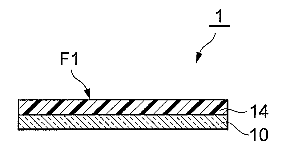
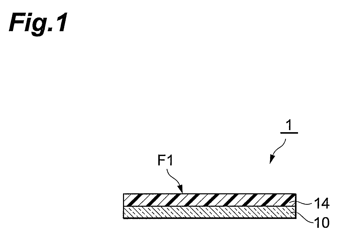
View moreImage
Smart ImageViewing Examples
Examples
examples
[0104]The present invention is described in additional detail by the examples that follow, but the present invention is not limited to these examples.
Login to View More PUM
| Property | Measurement | Unit |
|---|---|---|
| wavelength range | aaaaa | aaaaa |
| wavelength range | aaaaa | aaaaa |
| wavelength | aaaaa | aaaaa |
Abstract
A photosensitive resin composition comprising: (A) a binder polymer; (B) a photopolymerizable compound that has an ethylenically unsaturated bond; and (C1) a compound represented by general formula (1) below,wherein, at least one R represents a C1-10 alkoxy group or a C1-12 alkyl group; the sum of a, b, and c is 1 to 6; and when the sum of a, b, and c is 2 to 6, each R may be the same as or different from one another.
Description
[0001]This application is a Divisional application of application Ser. No. 11 / 915,169, filed Nov. 21, 2007, the contents of which are incorporated herein by reference in their entirety. No. 11 / 915,169 is a National Stage application, filed under 35 USC 371, of International (PCT) Application No. PCT / JP2006 / 310134, filed May 22, 2006.TECHNICAL FIELD[0002]The present invention relates to a photosensitive resin composition, a photosensitive element, a method for forming a resist pattern, and a method for producing printed wiring boards.BACKGROUND ART[0003]Microelectronic circuits, as encountered with, for example, wiring boards for plasma displays, wiring boards for liquid-crystal displays, large-scale integrated circuits, thin transistors, semiconductor packages, and so forth, are typically produced through a process known as photolithography that involves the formation of a resist pattern. In photolithography, a conductor pattern is formed on a substrate, for example, as follows. A p...
Claims
Login to View More Application Information
Patent Timeline
 Patent Type & Authority Applications(United States)
IPC IPC(8): G03F7/20G03F7/004
CPCC08F2/50G03F7/031Y10S430/146Y10S430/114Y10S430/106Y10S430/116Y10S430/121G03F7/0045G03F7/0047G03F7/027
Inventor MIYASAKA, MASAHIROKUMAKI, TAKASHI
Owner RESONAC CORPORATION
Features
- R&D
- Intellectual Property
- Life Sciences
- Materials
- Tech Scout
- Unparalleled Data Quality
- Higher Quality Content
- 60% Fewer Hallucinations
Learn More Browse by: Latest US Patents, China's latest patents, Technical Efficacy Thesaurus, Application Domain, Technology Topic, Popular Technical Reports.
© 2025 PatSnap. All rights reserved.Legal|Privacy policy|Modern Slavery Act Transparency Statement|Sitemap|About US| Contact US: help@patsnap.com


