
Cold cathode fluorescent lamp

a fluorescent lamp and cathode technology, applied in the direction of discharge tube/lamp details, discharge tube luminescnet screens, electric discharge lamps, etc., can solve the problems of electrode material more expensive than nickel, electrode forming difficult, electrode sputtering resistance is reduced, etc., to achieve excellent sputtering resistance, low cost, easy manufacturing

Inactive Publication Date: 2010-11-04
NEC LIGHTING +1
View PDF3 Cites 0 Cited by
  • Summary
  • Abstract
  • Description
  • Claims
  • Application Information

AI Technical Summary

Benefits of technology

[0009]It is an object of the present invention problem to provide a cold cathode fluorescent lamp comprising electrodes that have resistance to surface oxidation during manufacture, have excellent sputtering resistance and long life, even if high tube current is applied during the use of the lamp, and can be easily manufactured at low cost.

Problems solved by technology

However, on the other hand, the degradation of the lead wire, which occurs when the lead wire is welded to the electrode of such a high melting point sintered metal, and the degradation of the sealing members, which occurs when both ends of the transparent tube are sealed, have been problems.
Also, these electrode materials are more expensive than nickel, the forming of electrodes using these is difficult, and consumables, such as a jig used during forming, are necessary.
As a result, the electrodes are significantly expensive.
However, problems of the discharge lamp described in Patent Document 1 are that the configuration of the electrode is complicated, thereby, the number of manufacturing steps increases, and the adjustment of the manufacturing steps is complicated, decreasing manufacturing efficiency.

Method used


Image

  • Cold cathode fluorescent lamp
  • Cold cathode fluorescent lamp
  • Cold cathode fluorescent lamp

Examples


example 1

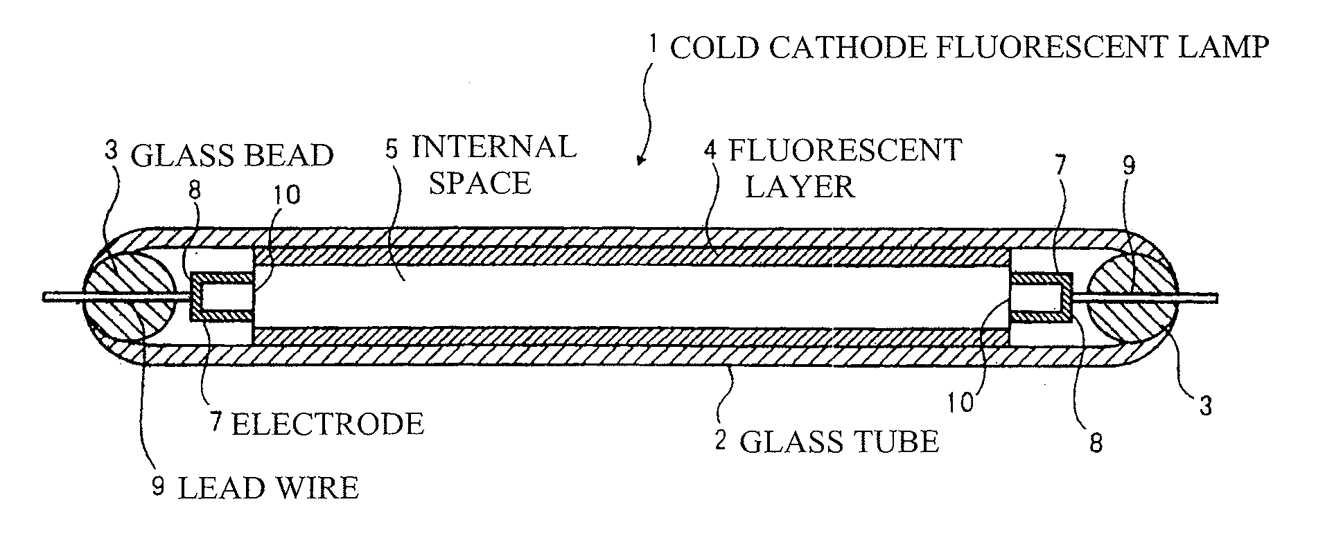
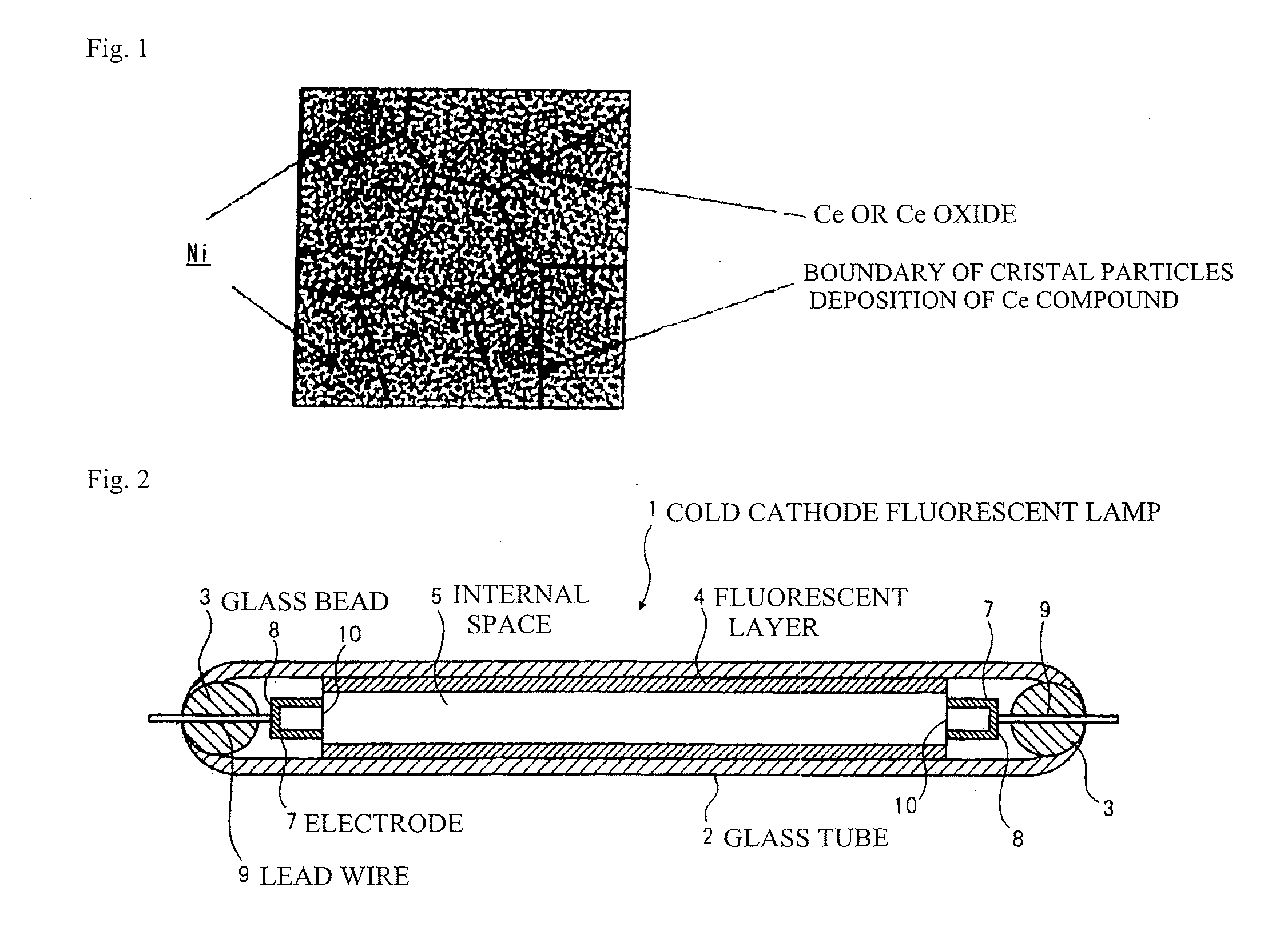
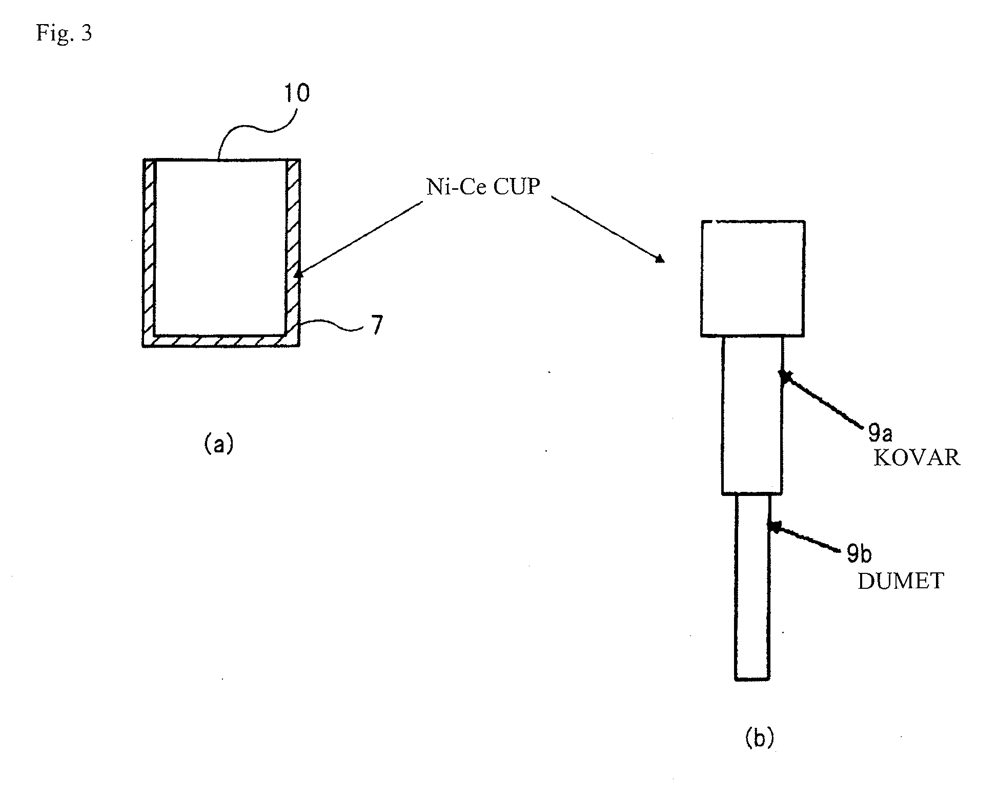
[0048]Starting raw materials, with 0.5% by mass of cerium metal added to nickel, were melted at a temperature equal to or higher than the melting point of nickel. This ingot material was cast in a mold and cooled to room temperature. Then, hot rolling, cold rolling, wire drawing, or the like was repeated to fabricate a wire material with a diameter of about 0.2 mm. The wire material was subjected to header working to fabricate a cup-shaped electrode with an outer diameter of 1.7 mm and a length of 5 mm. A Kovar wire with a diameter of 0.8 mm was welded to the bottom surface portion of the obtained electrode for integration.

[0049]The average diameter of crystal particles of the nickel of the electrode was measured by the comparison method. The average diameter of crystal particles of the nickel was 22 μm.

[0050]About 18 μm thick of a fluorescent material was applied to the inner wall surface of a glass tube with a bore of 2.0 mm. The electrodes to which the Kovar wire was fused were l...

examples 2 to 40

[0052]A cold cathode fluorescent lamp was fabricated and the sputtering resistance was evaluated for the obtained cold cathode fluorescent lamp as in Example 1 except that the starting raw materials were changed to a composition shown in Table 1. The result is shown in Table 1.


PUM


Abstract

There is provided a cold cathode fluorescent lamp that has excellent sputtering resistance and long life, even if high tube current is applied, and can be easily manufactured at low cost. In a cold cathode fluorescent lamp comprising a transparent tube having a fluorescent layer provided on an inner wall surface, containing a rare gas and mercury inside, and having both ends enclosed by sealing members, electrodes provided near both ends inside the transparent tube, and lead wires connected to the electrodes and provided through the sealing members, the electrode contains nickel as a main component and contains cerium metal or cerium oxide.

Description

TECHNICAL FIELD[0001]The present invention relates to a cold cathode fluorescent lamp, and more particularly to a cold cathode fluorescent lamp in which a longer life is intended by improving the sputtering resistance of the electrodes even if high tube current is applied.BACKGROUND ART[0002]Cold cathode fluorescent lamps are frequently used for backlights applied to liquid crystal displays such as for televisions or computers, light sources for reading for facsimiles or the like, light sources for the erasers of copying machines, various displays, or the like because the cold cathode fluorescent lamps are excellent in high brightness, high color rendering, long life, low power consumption, or the like. In this type of cold cathode fluorescent lamp, voltage is applied to electrodes provided near both ends of a transparent tube of glass or the like containing a rare gas and mercury airtight inside, to ionize the rare gas by a slight amount of electrons present in the transparent tube...

Claims


Application Information

Patent Timeline
Patent Type & Authority Applications(United States)
IPC IPC(8): H01J61/06
CPCH01J61/09H01J61/0675
Inventor SUGIMURA, TOSHIKAZUHATA, HITOSHISAWAYAMA, SHINOBUKAWANISHI, ISAOTAKAHASHI, TATSUYA
Owner NEC LIGHTING
Learn More