
Fishing rod holder mount

a technology for fishing rods and mounts, which is applied in the field of fishing rod mounts, can solve the problems of fishing rods being broken or damaged, fisherman have long been plagued by how to securely hold fishing rods in boats, and achieve the effects of simple and economical, light weight and portabl

Inactive Publication Date: 2010-10-28
GORDON JERRY
View PDF72 Cites 7 Cited by
  • Summary
  • Abstract
  • Description
  • Claims
  • Application Information

AI Technical Summary

Benefits of technology

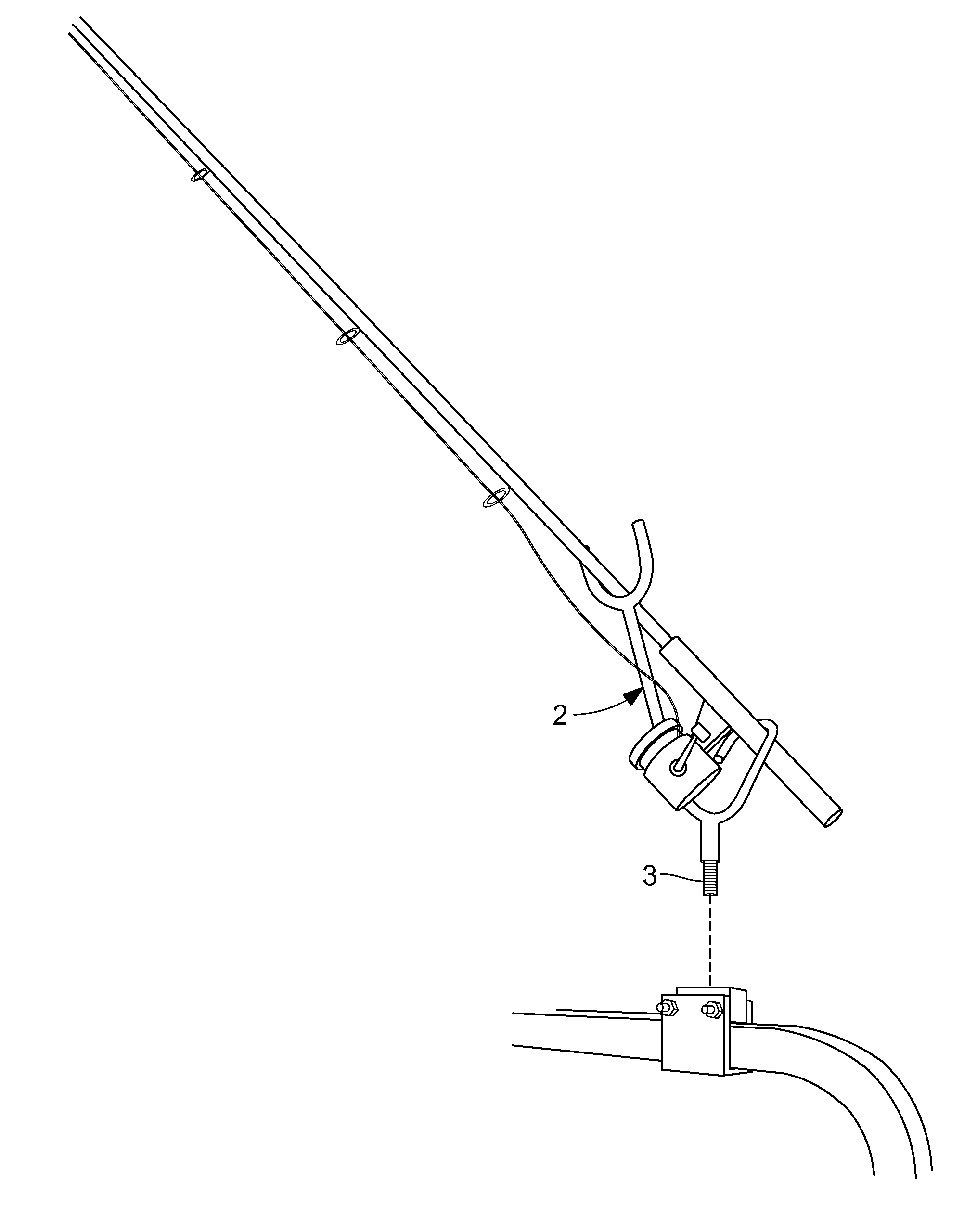
"The invention is a portable fishing rod holder mount that is light weight, portable, and easy to set up at any desired location. It securely holds a fishing rod in a stable manner and prevents damage. The mount includes a retaining member with a gap between its walls, a compression block, and a fastener that tightens the retaining member to securely hold the rod. The mount can be easily manufactured and is aesthetically pleasing. It is designed to be used on a boat rail and can be quickly and safely operated."

Problems solved by technology

Fishermen have long been plagued by how to securely hold a fishing rod in a boat, particularly while trolling or while on a fishing dock or pier while waiting for a fish to strike.
However, during trolling, if the lure or hook strikes an obstruction, the rod can be pulled out of the boat and the fisherman may either then lose their tackle, or the rod may broken or be damaged.
In addition, if one fisherman in a boat is trolling and another is casting, it often results in tangling of lines unless the rod under trolling can be kept in a low profile position that does not obstruct the casting of the other rod.
Many boats have lacked sufficient numbers of or had poorly positioned rod holders.
Usually, the limitations of prior art rod holders are due to an inability to effectively mount the rod holder.
A limitation of prior art rod holder mounts is that they cannot always mount in a convenient place.
However, most fishing rod holder mounts were only capable of being mounted in the floor of a boat.
Another limitation is that prior art holder mounts are not readily portable and selectively placeable.
Yet another limitation of many prior art rod holder mounts is the complexity of manufacturing the device.

Method used


Image

  • Fishing rod holder mount
  • Fishing rod holder mount
  • Fishing rod holder mount

Examples


Embodiment Construction

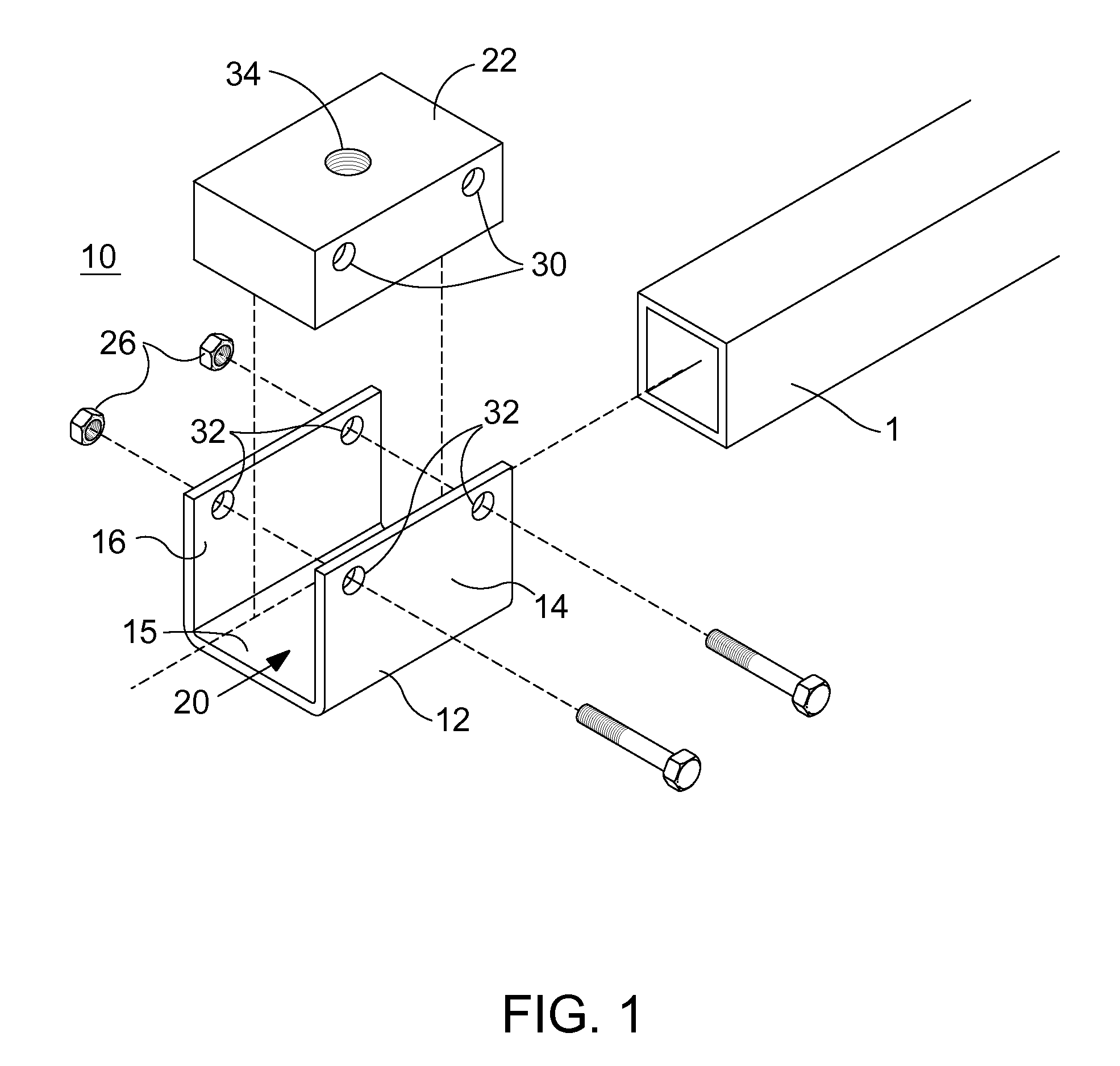
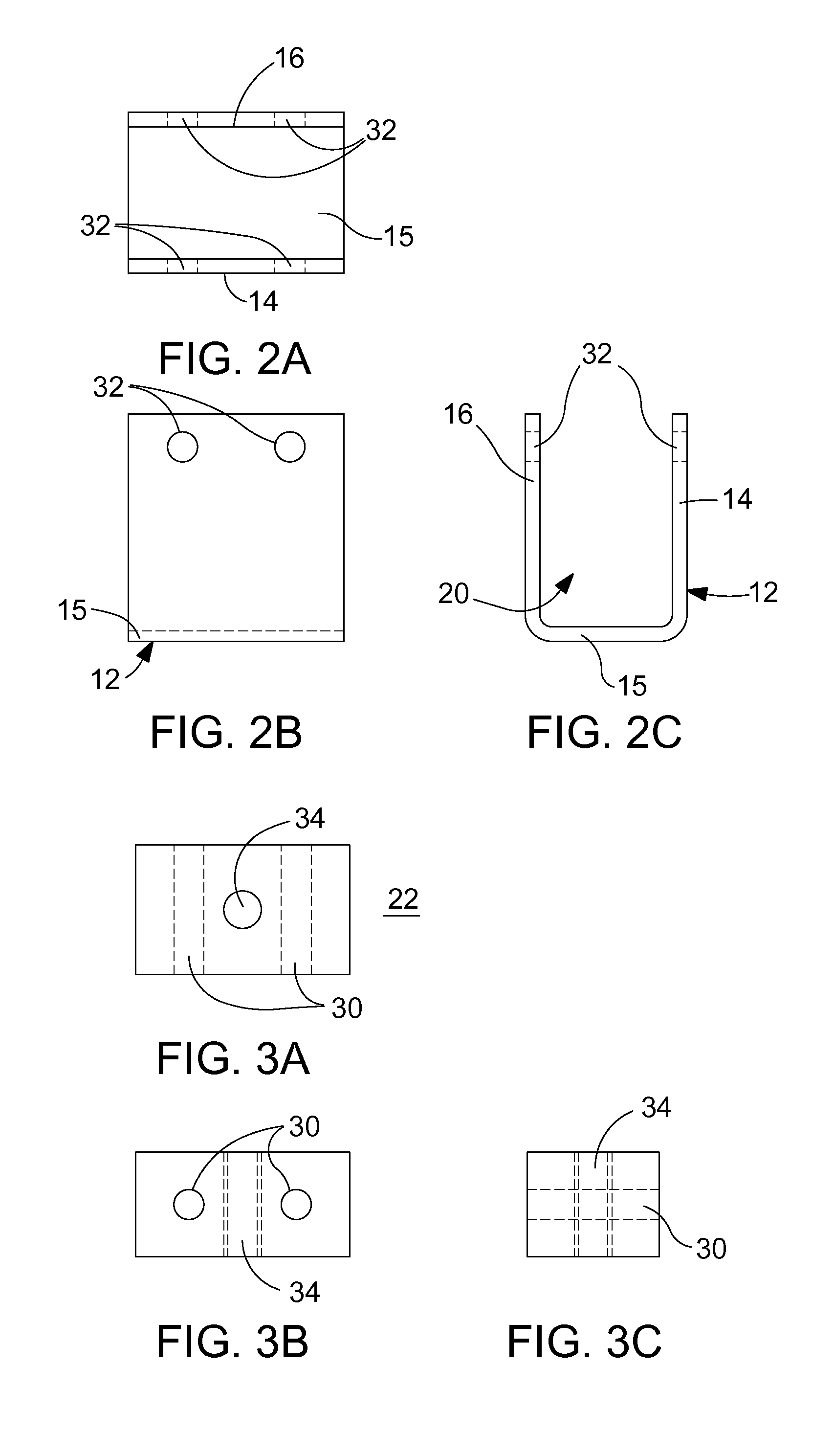
[0038]Referring now specifically to the drawings, a preferred embodiment of a fishing rod holder mount 10 according to the present invention is illustrated in FIGS. 1 through 4, and illustrated generally as reference numeral 10.

[0039]As best shown in FIG. 1, the mount 10 includes a U-shaped retaining member 12 having a pair of spaced-apart walls 14, 16, that are interconnected by a connecting wall 15. A gap 20 is defined between the pair of spaced-apart walls 14, 16. The U-shaped retaining member 12 may be configured in other suitable shapes, though it is shown in a U-shaped configuration in FIG. 1. A compression block 22 is configured for fitting into the gap 20 of the U-shaped retaining member 12. In one embodiment, the compression block 22 will have a width that is less than the width of gap 20. The compression block 22 includes a pair of apertures 30 for receiving threaded fasteners 24 that are also received within complementary apertures 32 of each wall of the pair of spaced-ap...


PUM


Abstract

A mount for being positioned on a rail and for receiving a fishing rod holder is provided. The mount includes a retaining member having a pair of spaced-apart walls that are interconnected on respective first ends by a connecting wall, the pair of spaced-apart walls defining a gap therebetween and a compression block selectively receivable within the gap of the retaining member and having a width that approximates a width of the rail. A fastener engages the compression block and extends from about respective second ends of each wall of the pair of spaced-apart walls and is configured such that tightening of the fastener deforms at least one wall of the pair of spaced-apart walls into engagement with the compression block, thereby providing an interference fit between the pair of spaced-apart walls of the retaining member and the rail.

Description

PRIORITY CLAIM[0001]This application claims priority to U.S. Provisional Patent Application No. 61 / 171,511 filed on Apr. 22, 2010, the contents of which are hereby incorporated by reference.TECHNICAL FIELD AND BACKGROUND OF THE INVENTION[0002]This invention relates to a fishing rod holder mount for selectively and temporarily being installed on a boat rail.[0003]Fishermen have long been plagued by how to securely hold a fishing rod in a boat, particularly while trolling or while on a fishing dock or pier while waiting for a fish to strike. Fishermen have tried to solve this problem by just laying the rod in the boat while trolling or laying the rod on the dock or pier. However, during trolling, if the lure or hook strikes an obstruction, the rod can be pulled out of the boat and the fisherman may either then lose their tackle, or the rod may broken or be damaged. If a fish violently strikes the boat or lure, the rod may be pulled overboard while trolling from a boat or while fishing...

Claims


Application Information

Patent Timeline
Patent Type & Authority Applications(United States)
IPC IPC(8): A01K97/10
CPCA01K97/10
Inventor GORDON, JERRY
Owner GORDON JERRY
Learn More