Continuous control of LED light beam position and focus based on selection and intensity control

a technology of intensity control and led light beam, applied in the field of lighting systems, can solve the problems of small room needs, inflexibility, and inefficiency, and achieve the effects of low cost, low cost, and easy and accurate measuremen

Inactive Publication Date: 2010-10-21
LITE ON TECH CORP
View PDF2 Cites 45 Cited by
  • Summary
  • Abstract
  • Description
  • Claims
  • Application Information

AI Technical Summary

Benefits of technology

[0011]According to another aspect of the invention the lighting system comprises a plurality of light units, wherein said light units are arranged in an array, wherein the light beams of substantially each pair of adjacent light units overlap each other, and wherein the light system comprises a light control means which is arranged to adjust the intensity of each one of said plurality of light units individually, wherein said light control means is further arranged to maintain the total combined luminous flux incident of said plurality of light units on a predefined imaginary flat surface substantially equal when adapting the intensity of the individual light units. Thereby a smooth transition is obtained, which is very close to the effect that is experienced by a user when a light beam is moved by physically moving the spotlight, or when the angle of the light beam of a spotlight would be changed by physically moving a lens. Moreover, the system is arranged thereby to provide a constant overall brightness experience to a user, independent of the angle with which the light beam strikes a surface (for instance a table or a floor).
[0023]All of the above-mentioned aspects of the invention provide, in a very efficient, cheap and reliable manner, the possibility to control the light system by hand gestures in directions substantially perpendicular to the axis of the ultrasound beam(s). If a reflecting object (such as a hand) is present in the beam, the position of the object in said directions can continuously be determined, and control of the various properties of the lighting system can be achieved thereby.
[0029]The ultrasonic transmitters may for instance emit sound at a frequency of 40 kHz. Although alternatives to the use of ultrasonic transmitters / receivers, such as for instance infrared or radar transmitters / receivers would be capable of measuring the time-of-flight of the respective signals, ultrasound is in particular suitable for the present application, since the time-of-flight (where the typical distance is between 0.2 and 2 meter) can be measured in milliseconds rather than in nanoseconds, which allows for easy and accurate measurement with low cost processing equipment. The system of the invention can be produced at very low cost, since piezoelectric acoustic transceivers are very cheap.
[0030]The system of the invention is easy to control, with a simple user interface which does not require additional equipment such as a remote control. Other qualities of the system of the invention are its robustness, its independency from environmental conditions, its one-dimensional recognition of control movements, and its low processing power requirements. The further advantage of an ultrasound sensor is that it is less influenced by changing ambient light, temperature and humidity conditions.
[0032]It is desirable that the ultrasound controlled lighting system is easy to produce in mass quantities, with low cost components, and has small dimensions so that it can be built-in in even in a small lamp.

Problems solved by technology

But in many cases only a small part of the room needs to be illuminated, which is not energy efficient.
Furthermore, in existing light applications light beam focussing and light beam position deviation is achieved in a mechanical way, which is not flexible and is vulnerable to mechanical failures.
A disadvantage of a remote control is the necessity of the presence of the remote control on the right location at a random moment.
Further, the different buttons on a remote control can be confusing to the user.
Finally, the costs of a remote control and the accompanying receiver are relatively high.
Such systems require heavy duty processing power, have a relatively long response time, and are relatively expensive.
Such an arrangement is however relatively expensive and inaccurate, as the intensity of the reflected infrared signal heavily depends on the kind of object that is moved in the beam.

Method used


Image

  • Continuous control of LED light beam position and focus based on selection and intensity control
  • Continuous control of LED light beam position and focus based on selection and intensity control
  • Continuous control of LED light beam position and focus based on selection and intensity control

Examples


example 1

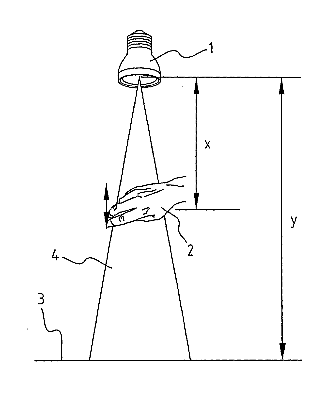
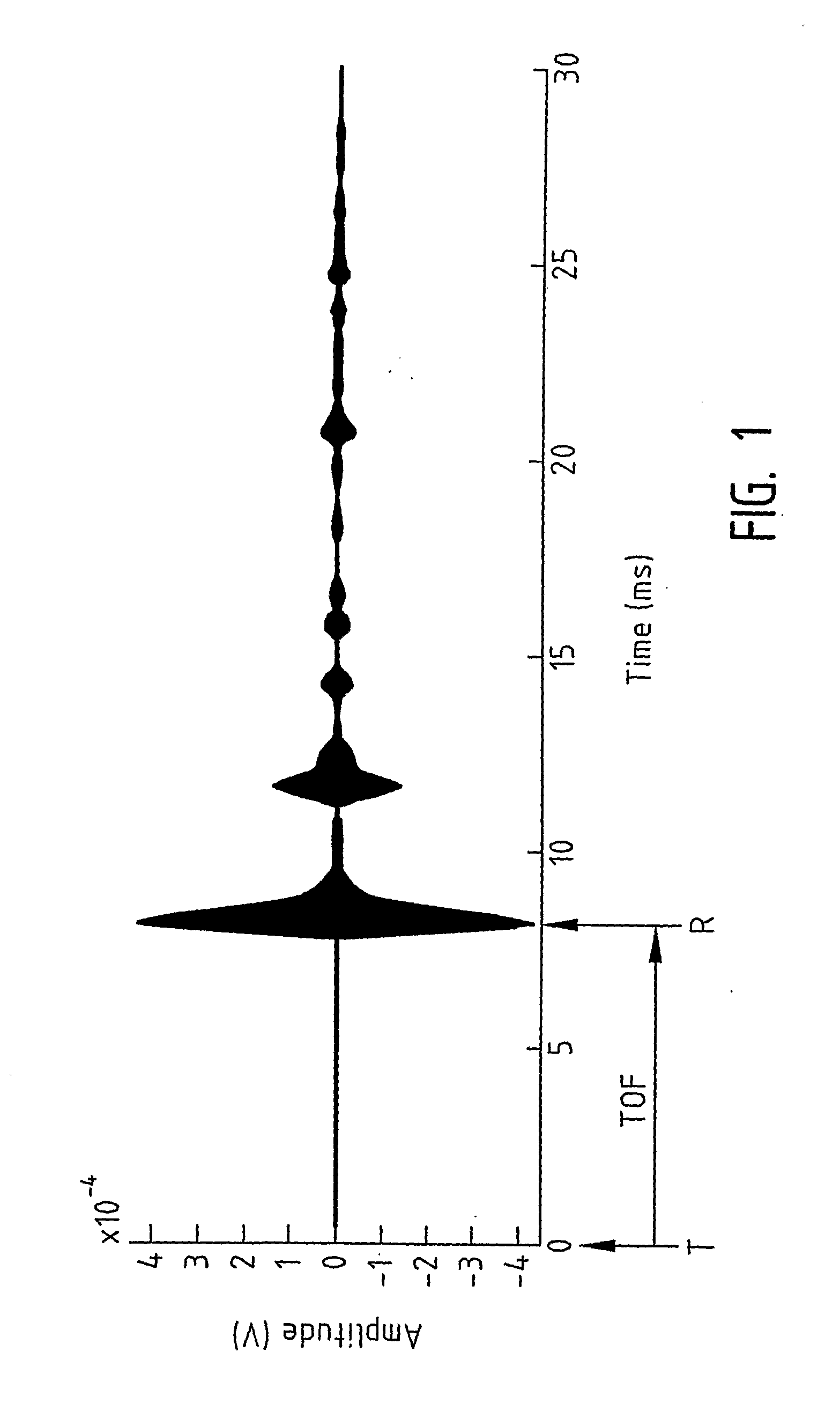
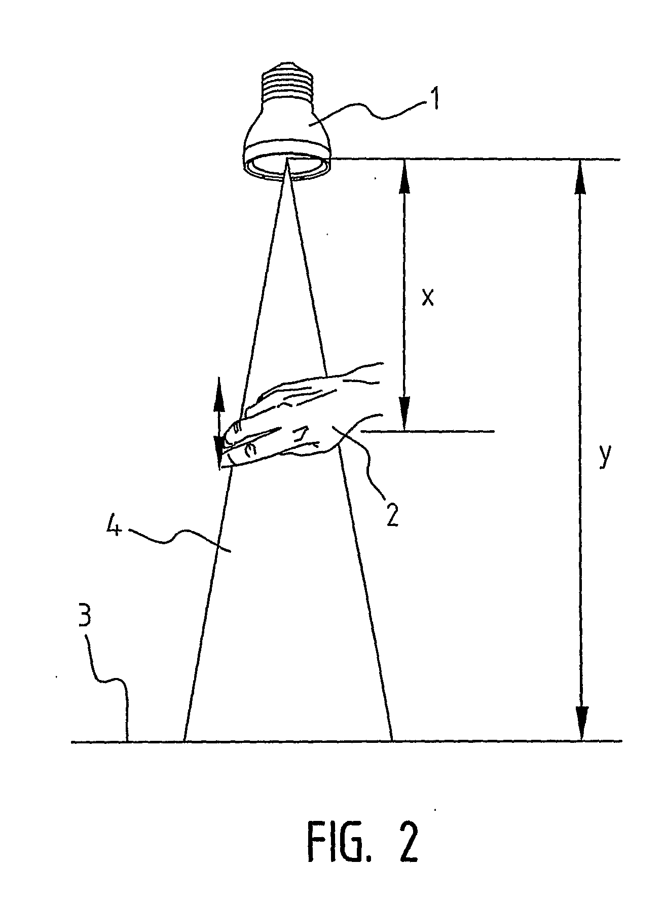
[0096]The number of sensors is two, one transceiver (transmitter & receiver) and one receiver.

[0097]The distance in a XY-plane can be calculated as follows:

vair·(TOFT1_R1)t=t0=(x1-x0)2+(y1-y0)2+(x0-x1)2+(y0-y1)2=avair·(TOFT1_R2)t=t0=(x1-x0)2+(y1-y0)2+(x0-x2)2+(y0-y2)2=b

[0098]where vair=speed of sound at room temperature, is 344 m / s.

[0099]To simplify the calculations the sensors are placed in the XY-plane. The receivers are placed so that both are on the X-axis and one on the Y-axis. The only parameter that has to be defined for the sensor units is the distance d, between the sensors. With these assumptions the new coordinates for the transmitter and the receivers become:

[0100]Receivers: R1=(0,0)

R2=(d,0)

[0101]Transmitter: T1=(0,0)

[0102]With the new coordinates above-mentioned expression become much easier to handle:

[0103]for t=t0:

a=2·(x0)2+(y0)2⇒(x0)2+(y0)2=a2b=(x0)2+(y0)2+(x0-d)2+(y0)2

[0104]The object position x0,y0 at t=t0 will be

(x0)t=t0=(a22+d2-b2-a·b)2·d(y0)t=t0=(a2)2-((x0)t=t0)...

example 2

[0109]In order to be able to determine the displacement of the object in the z-direction an additional transceiver is included. Determination of the displacement in the z-direction can be used for additional menu control. In this example one transmitter and three receivers are used, in a configuration as in FIG. 12. The basic principle is the same as in example 1. Time-of-flight measurements are performed on three sensors now instead of two: one transceiver and two receivers.

[0110]Distance calculation can be performed from the transmitter to the object (hand) and from the object to the three receivers by the following equations:

vair·(TOFT1,R1)t=t0=(x1-x0)2+(y1-y0)2+(z1-z0)2+(x0-x1)2+(y0-y1)2+(z0-z1)2vair·(TOFT1,R2)t=t0=(x1-x0)2+(y1-y0)2+(z1-z0)2+(x0-x2)2+(y0-y2)2+(z0-z2)2vair·(TOFT1,R3)t=t0=(x1-x0)2+(y1-y0)2+(z1-z0)2+(x0-x3)2+(y0-y3)2+(z0-z3)2

[0111]These are 3 equations with 3 unknowns. The calculation result is: (x0)t=t0, (y0)t=t0, (z0)t=t0. This is the initial position of the obje...

example 3

[0116]In this example a system with three transceivers is described, in a configuration as in FIG. 12. This provides the possibility to measure the object position three times from different transmitter positions.

[0117]First at t=t0 transmitter T1 will send an acoustic signal to the object. The signal will be reflected at the object and will be received by the three receivers (R1, R2, R3).

vair·(TOFT1,R1)t=t0=(x1-x0)2+(y1-y0)2+(z1-z0)2+(x0-x1)2+(y0-y1)2+(z0-z1)2vair·(TOFT1,R2)t=t0=(x1-x0)2+(y1-y0)2+(z1-z0)2+(x0-x2)2+(y0-y2)2+(z0-z2)2vair·(TOFT1,R3)t=t0=(x1-x0)2+(y1-y0)2+(z1-z0)2+(x0-x3)2+(y0-y3)2+(z0-z3)2

[0118]These are 3 equations with 3 unknowns. The calculation result is [(x0)t=t0]T1, [(y0)t=t0]T1, [(z0)t=t0]T1.

[0119]At t=t1 transmitter T2 will send an acoustic signal to the object. The signal will be reflected at the object and will be received by the three receivers.

vair·(TOFT2,R1)t=t1=(x2-x0)2+(y2-y0)2+(z2-z0)2+(x0-x1)2+(y0-y1)2+(z0-z1)2vair·(TOFT2,R2)t=t1=(x2-x0)2+(y2-y0)2+(z2...


PUM


Abstract

A lighting system comprising a plurality of light units, wherein said light units are arranged in an array, wherein the light beams of substantially each pair of adjacent light units overlap each other, and wherein the light system comprises a light control means which is arranged to adjust the intensity of each one of said plurality of light units individually, wherein said light control means is further arranged to maintain the total combined luminous flux incident of said plurality of light units on a predefined imaginary flat surface substantially equal when adapting the intensity of the individual light units.

Description

CROSS REFERENCE TO RELATED APPLICATION[0001]This application is the 35 U.S.C. §371 national stage of PCT application PCT / CN2007 / 003167, filed Nov. 8, 2007, the disclosure of which is hereby incorporated by reference.FIELD OF THE INVENTION[0002]The invention relates to a lighting system comprising a lamp arranged to transform electricity into a light beam having properties such as intensity, colour, colour temperature, direction and beam cone angle, and a light control means arranged to adjust said light beam properties.BACKGROUND OF THE INVENTION[0003]In existing lighting applications often a very wide illumination of the whole room is performed. But in many cases only a small part of the room needs to be illuminated, which is not energy efficient. Furthermore, in existing light applications light beam focussing and light beam position deviation is achieved in a mechanical way, which is not flexible and is vulnerable to mechanical failures.[0004]It is a goal of the invention to prov...

Claims


Application Information

Patent Timeline
IPC IPC(8): H05B37/02
CPCH03K17/94H05B37/0227H03K2217/94005H05B47/125Y02B20/40
Inventor VAN ENDERT, TONY PETRUSCHEN, TZU-NAN
Owner LITE ON TECH CORP
Why Eureka
Try Eureka