
Method and device for determining the moisture content and conductivity in the ground and in bulk materials

a technology of conductivity and ground, applied in resistance/reactance/impedence, material analysis, instruments, etc., can solve the problems of difficult evaluation of tdr signals, high cost of cable testers and evaluation units with the required resolution capability for travel time measurements in connection therewith, and small influence of conductivity with increasing frequency. , to achieve the effect of simple and accurate measuremen

Inactive Publication Date: 2006-10-24
GSF FORSCHUNGSZENT FUR UMWELT & GESUNDHEIT
View PDF11 Cites 15 Cited by
  • Summary
  • Abstract
  • Description
  • Claims
  • Application Information

AI Technical Summary

Benefits of technology

"The patent describes a method and device for measuring moisture content and conductivity in ground and bulk materials using a capacitive sensor. The sensor is charged from a constant external voltage supply and the charging time is measured. The water content and conductivity can be determined by analyzing the charging times or the voltage / time diagram. The method is simple and accurate, and the device is portable and easy to use. The technical effects of the invention include improved efficiency and accuracy in measuring moisture content and conductivity in ground and bulk materials."

Problems solved by technology

The evaluation of a TDR signal is difficult.
The cable tester required and an evaluation unit with the required resolution capability for travel time measurements needed in connection therewith is very expensive.
However, this influence of the conductivity becomes smaller with increasing frequency.
For the determination of the complex resistance with a real and an imaginary component again a network channel analyzer is required which increases the expenses for a simultaneous determination of the moisture content and the conductivity.

Method used


Image

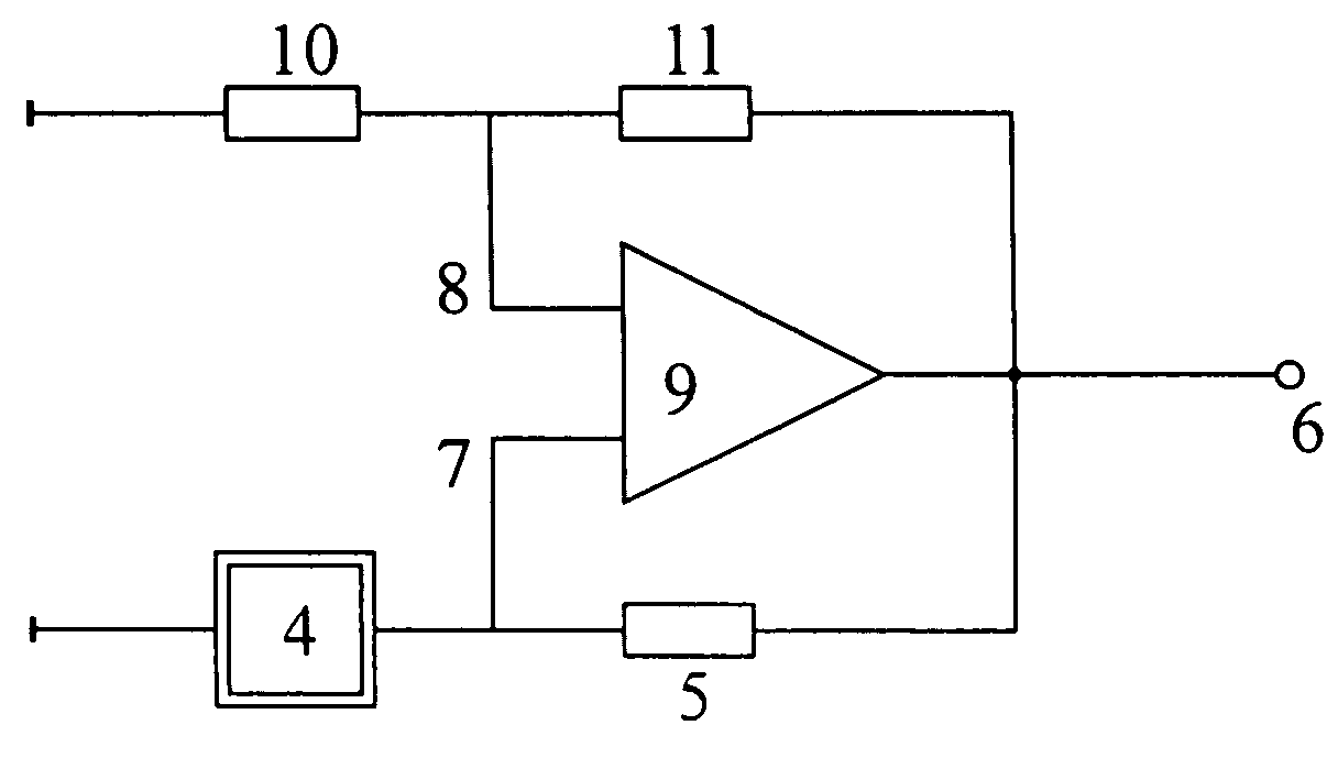
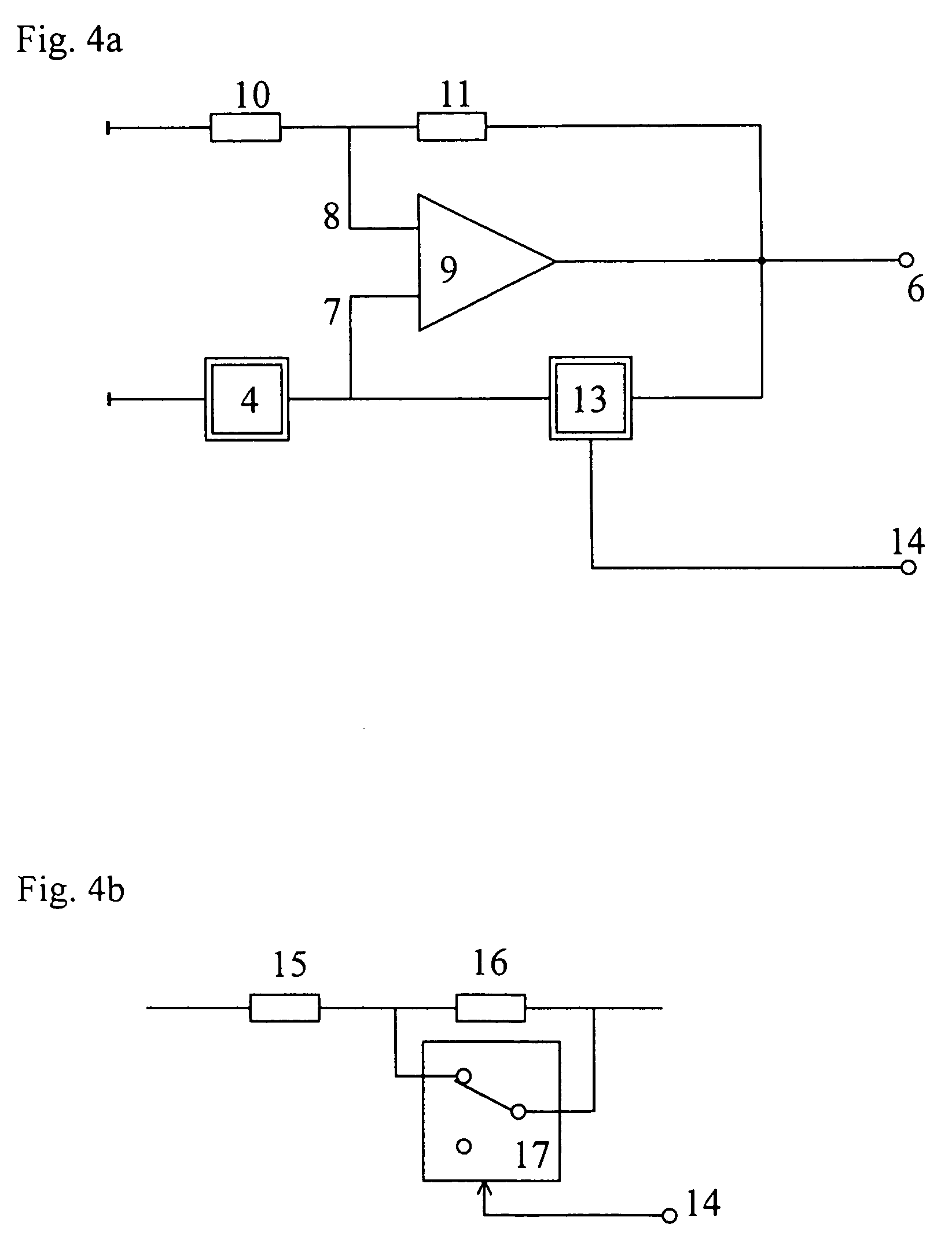
  • Method and device for determining the moisture content and conductivity in the ground and in bulk materials
  • Method and device for determining the moisture content and conductivity in the ground and in bulk materials
  • Method and device for determining the moisture content and conductivity in the ground and in bulk materials

Examples


Embodiment Construction

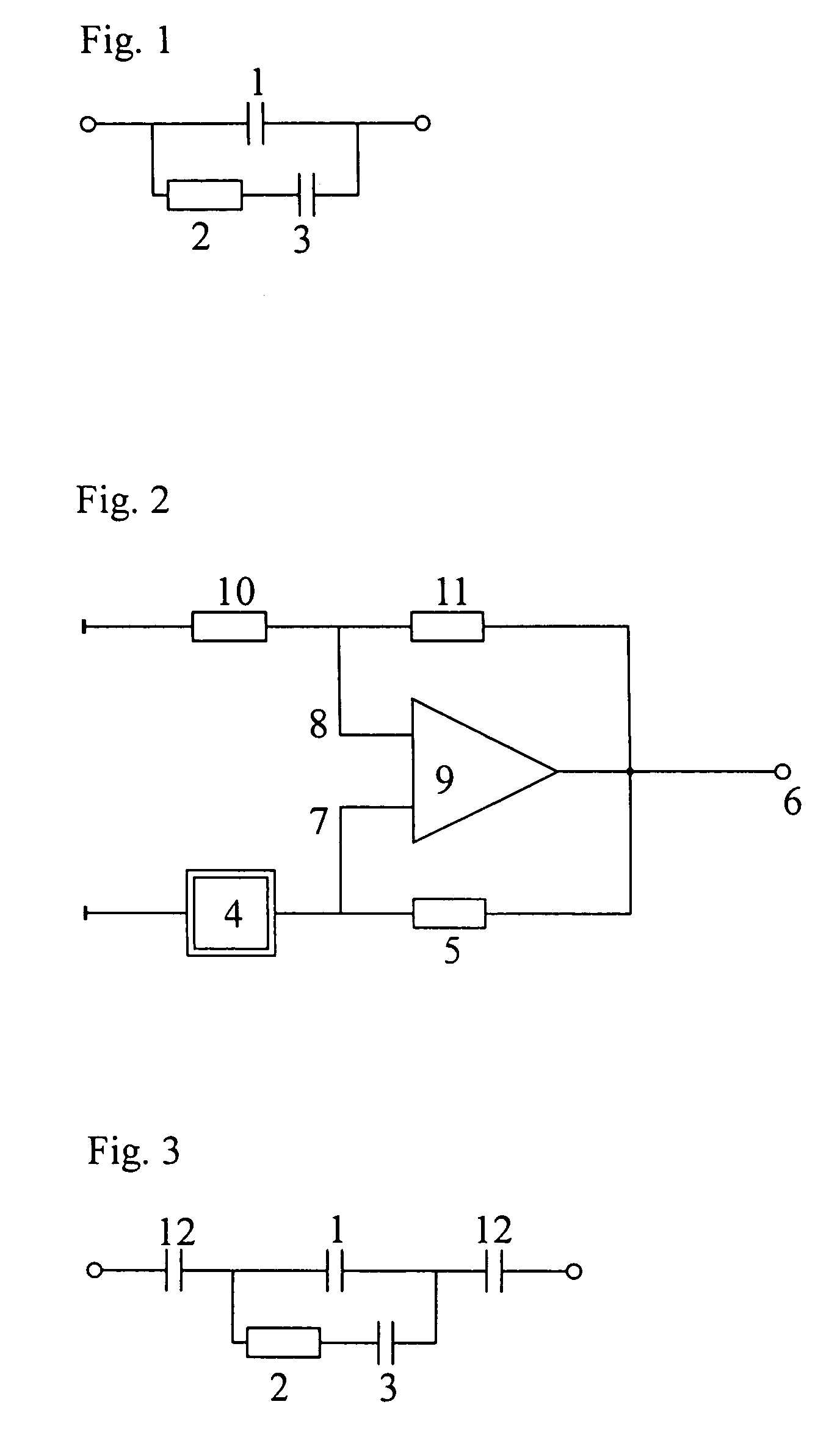
[0028]FIG. 1 shows the substitute circuit of the sensor in a soil segment or in a bulk material.

[0029]Basically, the conductivity σm of a material can be represented by a resistance Rs which is arranged parallel to Cs. Rs and σm have the relationship,

Rs=G / σm   (2)

wherein G is a constant geometry-dependent factor of the sensor which can be determined by a calibration measurement.

[0030]With their large dipole moments which align themselves in a magnetic field, water molecules affect the dielectric constant of a material εw to a large degree. The electric conductivity in the water is furthermore not a metallic conductivity with movable charges and an opposite charge at the stationary phase, but an ionic conductivity. That means that the electric field applied separates the charges because of the conductivity present as much as possible and pulls them further apart so that a dipole is induced. The dipoles drift apart until the electric field of the separated ions formed thereby compensa...


PUM

PropertyMeasurementUnit
conductanceaaaaaaaaaa
capacitance Csaaaaaaaaaa

Abstract

In a method and device for determining the moisture content and conductivity in the ground and in bulk materials, a capacitive sensor is disposed in the ground or the bulk material, the sensor is charged from a constant external voltage supply with a given initial current from a given first voltage threshold value to a given second voltage threshold value and either a voltage / time diagram is determined or a first charging time required for charging the sensor from the first to the second voltage threshold values by the constant external voltage supply is determined and a second charging time is determined wherein either the initial current and / or at least one of the two voltage threshold values are altered and the water content and the conductivity are determined by verification of the two charging times or of the voltage / time diagram.

Description

[0001]This is a Continuation-In-Part application of International Application PCT / EP2003 / 012040 filed Oct. 30, 2003 and claiming the priority of German application 102 56 064.1 filed Nov. 30, 2002.BACKGROUND OF THE INVENTION[0002]The invention resides in a method and a device for determining the moisture content and conductivity in the ground and in bulk materials by way of a capacitive sensor introduced into the ground or the bulk material which is charged by a voltage and determining the time required for the charging of the sensor.[0003]As a reliable measure for determining the moisture content in a soil sample or a bulk material the dielectric constant εm between two electrodes is used. In comparison with many other materials water has a very high dielectric constant so that already a small moisture content of the measuring volume that is in the soil sample or in the bulk material results in a significant change of the dielectric constant εm. Typical areas of application include...

Claims


Application Information

Patent Timeline
Patent Type & Authority Patents(United States)
IPC IPC(8): G01R27/26G01N27/22G01N33/24
CPCG01N27/223G01N33/246
Inventor BERNHARD, RUTH
Owner GSF FORSCHUNGSZENT FUR UMWELT & GESUNDHEIT
Learn More