
Diagnostic method for motor

a technology for diagnostic devices and motor units, which is applied in the direction of electric devices, motor/generator/converter stoppers, propulsion parts, etc., can solve the problems of difficult to measure the degradation state or the like of oil, and achieve the effect of easy measurement and high cooling effect of the motor uni

Inactive Publication Date: 2013-12-26
NTN CORP
View PDF9 Cites 16 Cited by
  • Summary
  • Abstract
  • Description
  • Claims
  • Application Information

AI Technical Summary

Benefits of technology

The present invention provides a diagnostic device and method for measuring the degradation state of oil in an electric vehicle's motor unit. This allows for easy detection of abnormalities in the oil supply system, prevention of malfunctions in the reduction gear unit, and maintenance of a high cooling effect on the motor unit. The device includes an oil degradation / others detection unit that can detect the contamination degree of the oil by measuring light transmittance, and the motor unit can be quickly repaired or replaced if necessary. The in-wheel motor drive apparatus is particularly vulnerable to abnormalities, and the detection of abnormalities can prevent damage to the motor unit and reduce the risk of vehicle failure. The reduction gear unit, which is in the form of a cycloidal gear device, allows for a smaller motor unit size and increased drive torque transmission to the wheel. The detection value of the oil degradation / others detection unit is sent or the start of rotation of the motor unit is not permitted, allowing for early diagnosis and repair of abnormalities.

Problems solved by technology

However, air is mixed into the oil during rotation of the reduction gear unit, and thus it is difficult to measure the degradation state or the like of the oil.
Thus, it is difficult to measure the degradation state or the like of the oil.

Method used


Image

  • Diagnostic method for motor
  • Diagnostic method for motor
  • Diagnostic method for motor

Examples


Embodiment Construction

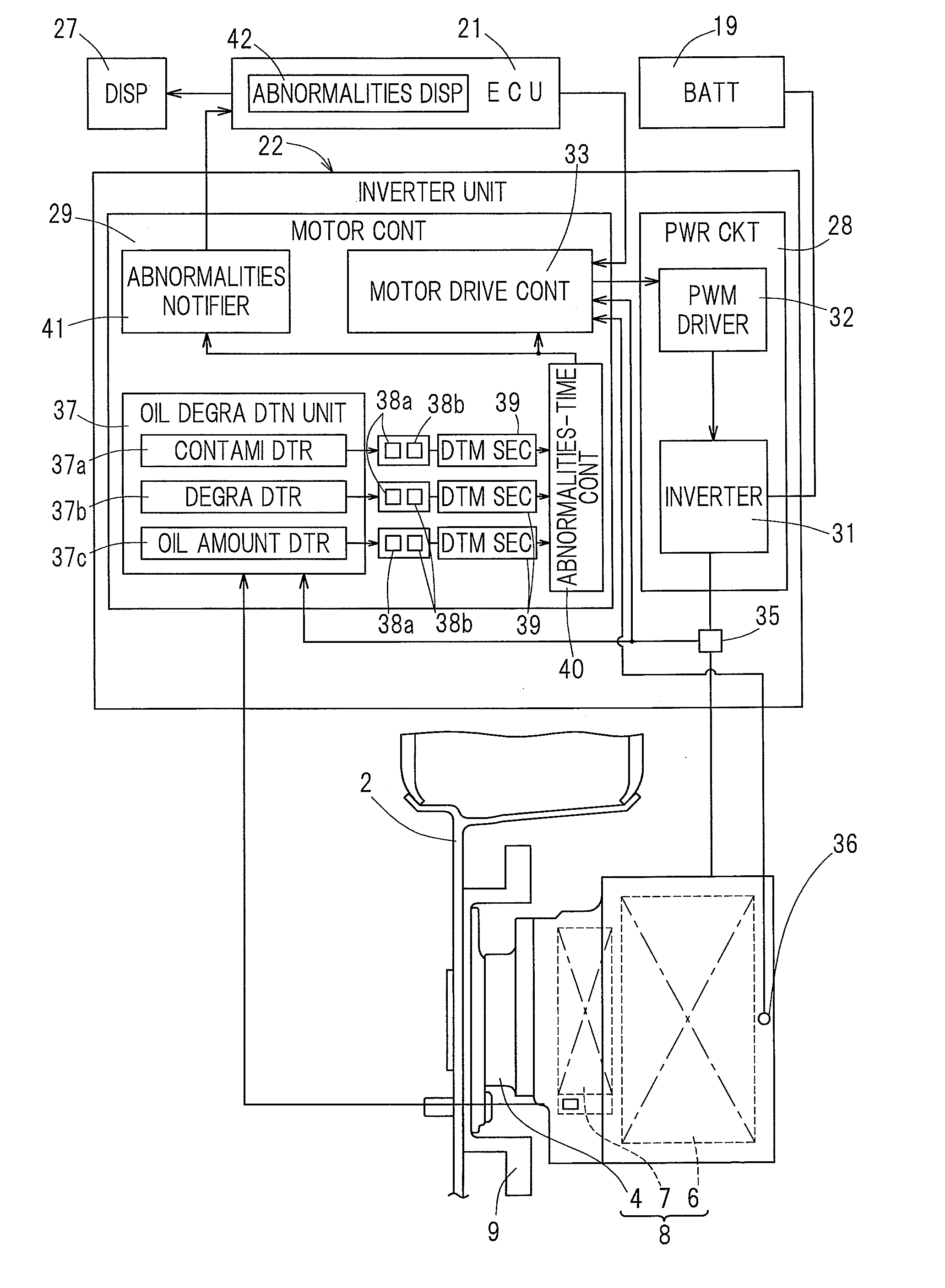
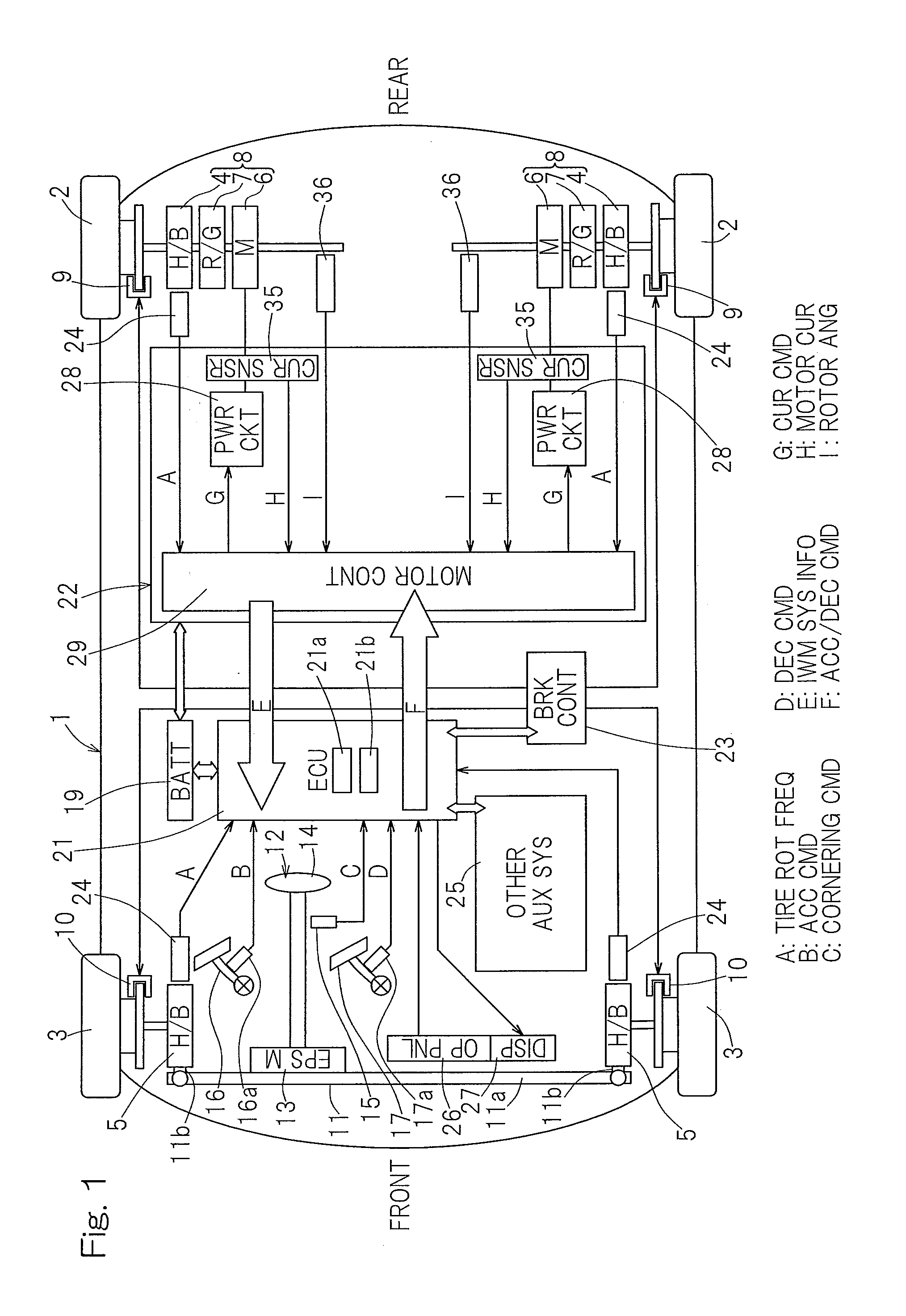
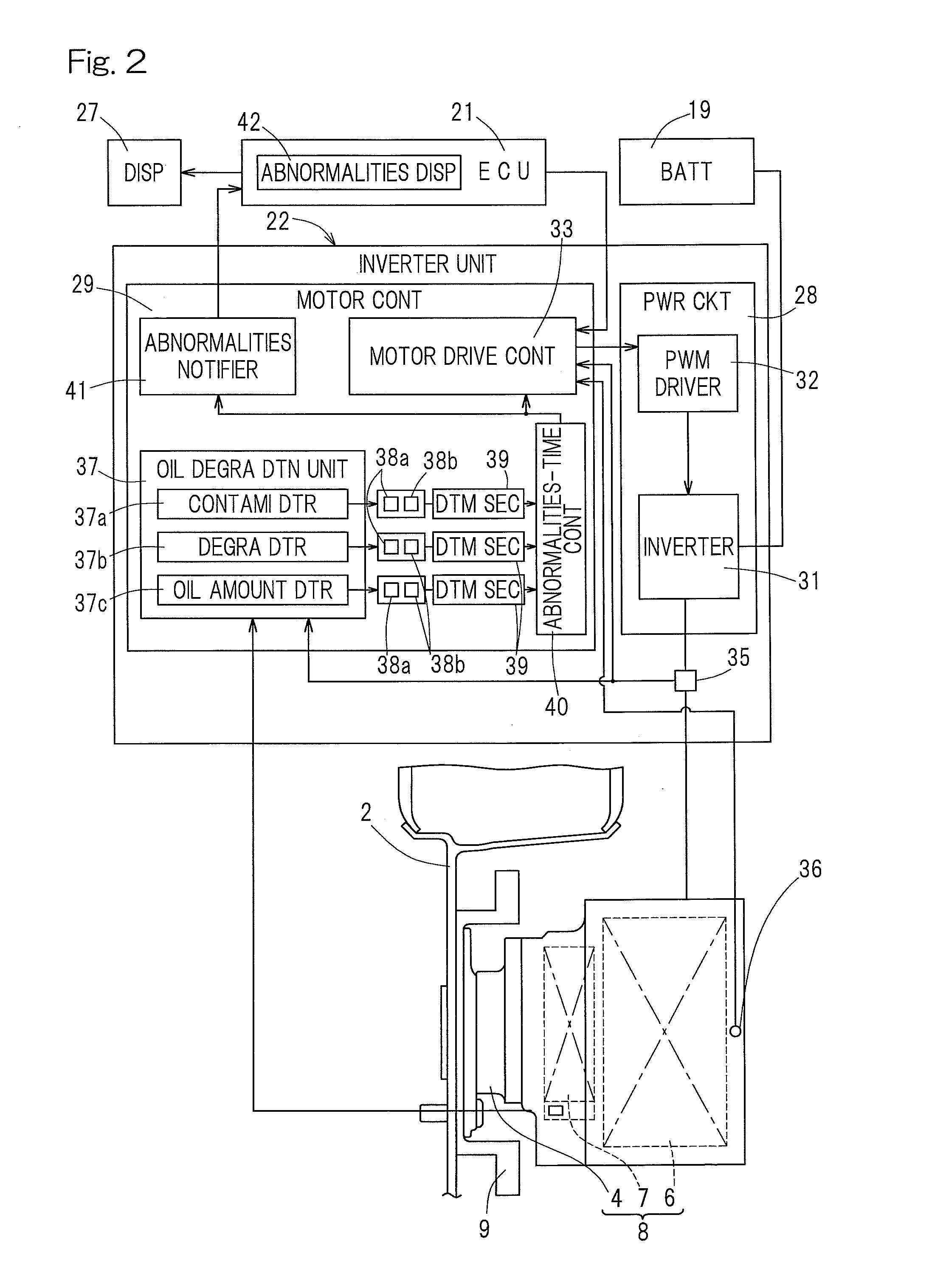
[0038]A diagnostic device and a diagnostic method for a motor unit of an electric vehicle according to one embodiment of the present invention will be described in connection with FIGS. 1 to 10. The diagnostic device for the motor unit is installed in the electric vehicle. As shown in FIG. 1, the illustrated electric vehicle is a four-wheel vehicle that includes a vehicle body 1 with left and right rear wheels 2 and left and right front wheels 3, with the rear wheels 2 being drive wheels and the front wheels 3 being steer idler wheels. The drive wheels 2 and the idler wheels 3, both equipped with tires, are supported by the vehicle body 1 via respective wheel bearing units 4, 5. In FIG. 1, the wheel bearing units 4, 5 are labeled with “H / B” which is an abbreviation for hub bearing. The left and right drive wheels 2, 2 are driven by respective independent traction motor units 6, 6. Rotation of the motor unit 6 is transmitted via a reduction gear unit 7 and a wheel bearing unit 4 to a...


PUM


Abstract

In a diagnostic device and a diagnostic method for a motor unit of an electric vehicle, an oil degradation / others detection unit is provided which is configured to detect at least any one detection item of a contamination degree, a degradation degree, and an oil amount of an oil used for cooling a motor unit or a reduction gear unit during a non-traveling period when the vehicle is powered on. An abnormalities-time control unit is provided which is configured to send notice of abnormalities of an oil supply system or not permit start of rotation of the motor unit when a detection value detected by the oil degradation / others detection unit is out of a setting range.

Description

CROSS REFERENCE TO THE RELATED APPLICATION[0001]This application is based on and claims Convention priority to Japanese patent application No. 2011-051383, filed Mar. 9, 2011, the entire disclosure of which is herein incorporated by reference as a part of this application.BACKGROUND OF THE INVENTION[0002]1. Field of the Invention[0003]The present invention relates to a diagnostic device and a diagnostic method for a motor unit of an electric vehicle, and relates to a self-diagnosis function of an oil supply system that supplies an oil used for lubricating a reduction gear unit or cooling the motor unit.[0004]2. Description of Related Art[0005]An electric vehicle may experience a malfunction of a motor unit for driving the vehicle or a malfunction of a controller that controls the motor unit. This can significantly affect the travel performance or travel safety. In particular, in the case where an in-wheel motor drive apparatus is used in an electric vehicle, rapid rotation of a whee...

Claims


Application Information

Patent Timeline
Patent Type & Authority Applications(United States)
IPC IPC(8): B60L3/04
CPCB60L3/04B60K7/0007B60K2007/0092B60L3/0061B60L15/2036B60L15/2072B60L2240/36B60L2240/425B60L2240/427B60L2240/429B60L2240/80B60L2250/10B60L2250/16B60W50/0205B60W2050/022B60L53/16F16H1/32F16H57/0405F16H57/0476G01N33/2888Y02T10/64Y02T10/70Y02T10/7072Y02T10/72Y02T90/14
Inventor OZAKI, TAKAYOSHI
Owner NTN CORP
Learn More