LED lamp structure

a technology of led lamps and lampshades, which is applied in the direction of planar light sources, semiconductor devices of light sources, lighting and heating apparatuses, etc., can solve the problems of reduced lighting efficiency and brightness, inconvenient user activities, and inability to smoothly discharge fluorescent tubes, etc., to achieve reduced power consumption, reduce manufacturing costs, and prolong service life

Inactive Publication Date: 2010-10-14
CHIEN HSIAO LOU
View PDF4 Cites 33 Cited by
  • Summary
  • Abstract
  • Description
  • Claims
  • Application Information

AI Technical Summary

Benefits of technology

[0005]A primary object of the present invention is to provide an LED lamp structure that has prolonged service life and reduced power consumption, and can be manufactured at reduced cost.
[0006]Another object of the present invention is to provide an LED lamp structure that includes radiating fins, via which heat produced by LED chips of the lamp structure can be radiated into ambient air, so that the problem of lowered lighting power of LED chips due to overheating is solved without adversely affecting the illuminating brightness of the LED lamp structure.
[0007]A further object of the present invention is to provide an LED lamp structure that can be expanded in both horizontal and vertical directions.
[0008]A still further object of the present invention is to provide an LED lamp structure that can illuminate in two opposite directions.

Problems solved by technology

After having been used for about 6,000 hours, the mercury vapor in the fluorescent tube is almost completely absorbed into the glass tube, and the fluorescent tube can no longer function to smoothly discharge and finally becomes burned-out.
It is of course inconvenient for the user to do so.
The overheated LED will have reduced lighting efficiency and decreased brightness.

Method used


Image

  • LED lamp structure
  • LED lamp structure
  • LED lamp structure

Examples


Embodiment Construction

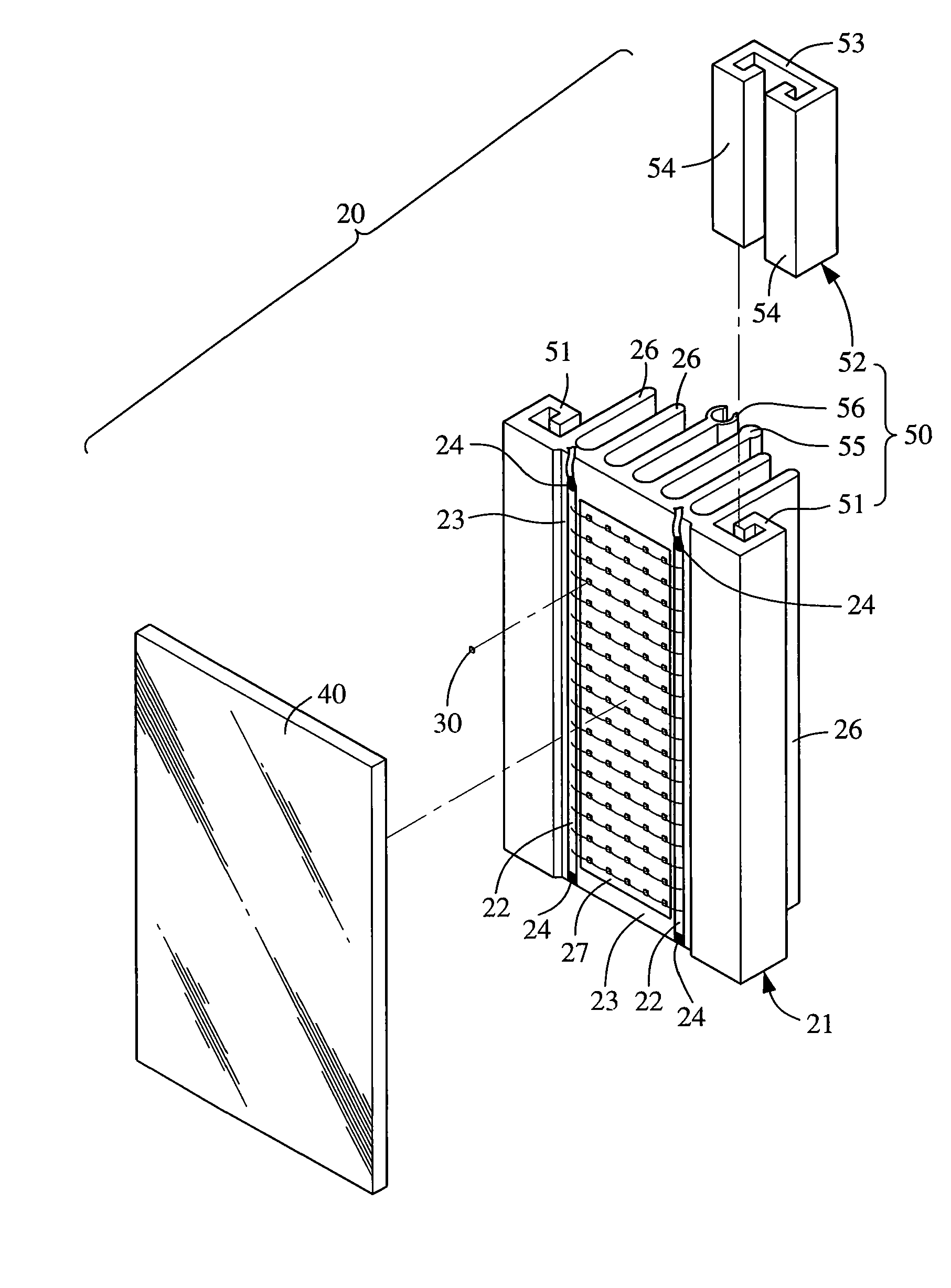
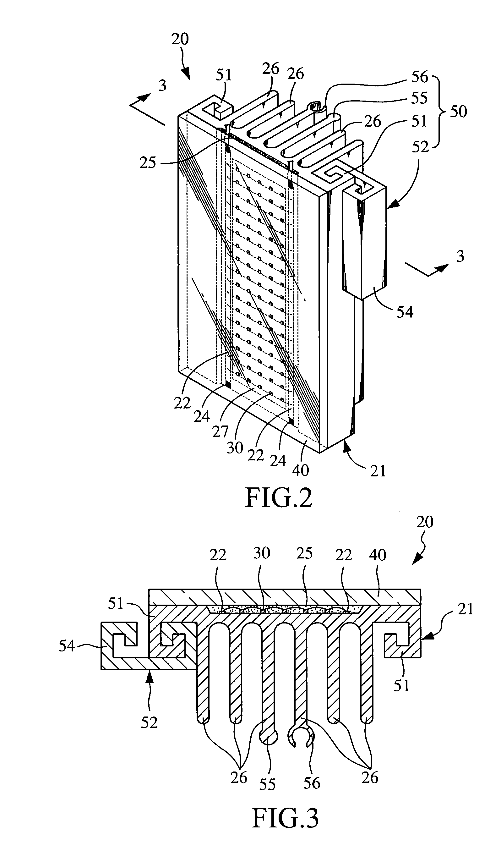
[0020]Please refer to FIGS. 2 to 4. An LED lamp structure 20 according to a preferred embodiment of the present invention includes a lamp body 21, a plurality of LED chips 30, a lens 40, and an expansion structure 50.

[0021]The lamp body 21 is made of a material with good heat radiating capacity, and defines a recess 23 on a front side thereof. A positive and a negative conducting wire 22 are provided in the recess 23, and a metal foil 27 is arranged between the positive and the negative conducting wire 22. The LED chips 30 are mounted on the metal foil 27 and are serially and parallelly connected to one another. The LED chips 30 are also electrically connected to the positive and the negative conducting wire 22 through wire bonding to thereby electrically connect with a plurality of wiring junctions 24. An encapsulating material 25 is filled in the recess 23 to complete packaging of the LED chips 30, while light emitted from the LED chips 30 can transmit through the encapsulating ma...


PUM


Abstract

An LED lamp structure includes a lamp body, a plurality of LED chips, a lens, and an expansion structure. The lamp body has a front side formed with a recess and a rear side formed with a plurality of radiating fins. A positive and a negative conducting wire are provided in the recess, and a metal foil is arranged between the positive and the negative conducting wire. The LED chips are mounted on the metal foil and electrically connected to the positive and negative conducting wires through wire bonding, so as to electrically connect to a plurality of wiring junctions. An encapsulating material is filled in the recess to complete packaging of the LED chips. The lens is mounted to the front side of the lamp body. A plurality of the lamp bodies can be connected side-by-side, end-to-end and / or back-to-back via the expansion structure to expand the LED lamp structure.

Description

FIELD OF THE INVENTION[0001]The present invention relates to an LED lamp structure, and more particularly to an LED lamp structure that is configured to enable radiation of heat produced by LED chips thereof and thereby avoids reduced lighting power due to overheating.BACKGROUND OF THE INVENTION[0002]Light plays a very important role in people's daily life to illuminate spaces inside and outside buildings. A fluorescent tube is currently the most common light source. To obtain good light scattering effect, a lamp is usually installed at a relatively high position, such as on a ceiling. As it is known, the fluorescent tube is a gas-discharge lamp that uses electricity to excite mercury vapor sealed in the lamp tube. The excited mercury vapor atoms produce short-wave ultraviolet light that then causes a fluorescent powder coated on the glass fluorescent tube of the lamp to fluoresce and thereby produces light. After having been used for about 6,000 hours, the mercury vapor in the fluo...

Claims


Application Information

Patent Timeline
Patent Type & Authority Applications(United States)
IPC IPC(8): F21V1/00
CPCF21S2/005F21V29/004F21Y2101/02F21Y2105/001F21V29/763F21Y2103/003F21K9/17F21V29/74F21V29/75F21K9/30F21K9/20F21Y2105/10F21K9/27F21Y2103/10F21Y2115/10
Inventor CHIEN, HSIAO-LOU
Owner CHIEN HSIAO LOU
Why Eureka
Try Eureka