
Peer-to-peer communication in wireless sensor network through delay response between packets

Inactive Publication Date: 2010-10-07
NANYANG TECH UNIV +1
View PDF5 Cites 7 Cited by
  • Summary
  • Abstract
  • Description
  • Claims
  • Application Information

AI Technical Summary

Benefits of technology

[0019]The delay time may be less than the count time. For instance, the delay time may be 40 to 50 percent of the count time, and preferably about 50 percent of the count time. The delay time may also be greater than a propagation time between the first node sending a packet to the second node and the second node receiving the packet from the first node. The delay time may also reduce error sensitivity of the second node determining the data due to variations in a propagation time between the first node sending a packet to the second node and the second node receiving the packet from the first node.
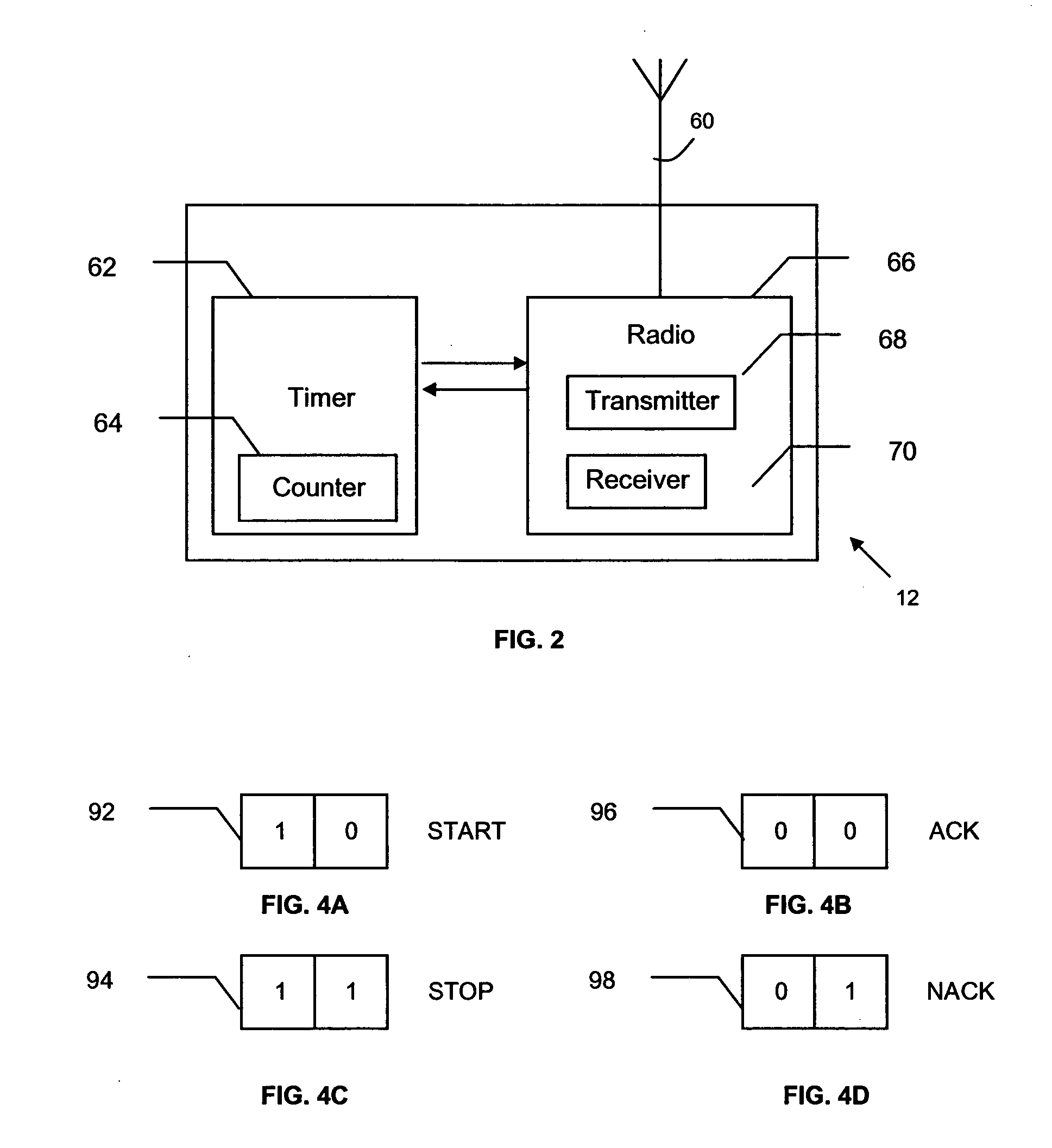
[0020]The first node may append padded bits to the data and stop the first counter and then send the second node the stop packet in response to the first node determining that the number of accumulated first counts corresponds to the data and the padded bits, and the second node may determine the data and the padded bits based on the number of accumulated second counts and then determine the data by stripping the padded bits. The padded bits may have a predetermined value about half-way between a maximum value and a minimum value and independent of the data. For instance, the padded bits may have a most significant bit set to a first binary value and remaining bits set to a second binary value. The padded bits may also have a greater bit length than the start and stop packets. For instance, the padded bits may be three bits and the start and stop packets may each be two bits. The padded bits may also reduce error sensitivity of the second node determining the data due to variations in a propagation time between the first node sending a packet to the second node and the second node receiving the packet from the first node.
[0024]Another advantage is that the second node starts the timer upon receiving the start packet and starts the second counter after the delay time expires, thereby introducing an artificial delay that reduces error sensitivity to transmission and propagation variations between the start and stop packets. As a result, the second node is less susceptible to delay variations between the start and stop packets that might otherwise corrupt the data.
[0025]Another advantage is that the first node appends the padded bits and the second node strips the padded bits, thereby introducing redundant bits that improve error control. As a result, the second node is less susceptible to data errors that exceed a clock cycle.
[0026]Another advantage is that the first and second nodes engage in a handshaking protocol using the acknowledge and non-acknowledge packets, thereby conserving power at both the first and second nodes in the event a start or stop packet is lost.

Problems solved by technology

Wireless sensor networks suffer from serious energy constraints since the sensor nodes are powered by a battery.
As power consumption is proportional to the length of data bits transmitted, the data suppression in VCDR reduces transmission and reception power.
A challenge is framing in which the optimal length of data to be sent has to be determined.
Shorter data leads to higher energy consumption due to more start and stop packets whereas longer data may introduce excessive delay.
Adding a node unique address to the packet header increases overhead and lowers efficiency.
Another challenge is sequencing.
An additional challenge is contention control.
Although the start and stop packets are relatively short, packet collision may occur.
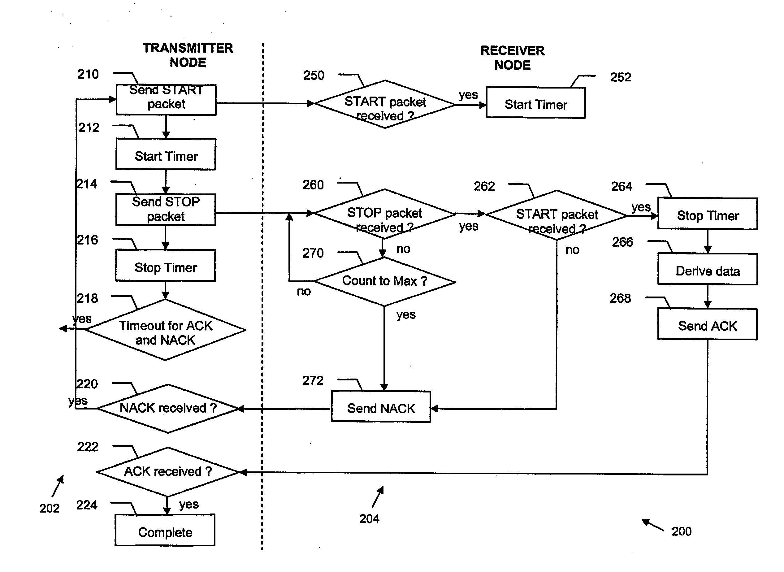
A further challenge is error control.
A first drawback of VCDR is time synchronization between the transmitter and receiver nodes.
Delay variations between the start and stop packets due to transmission and propagation variables can easily corrupt the data and render VCDR impractical.
Another drawback of VCDR is the lack of error control techniques.
Since VCDR is a relatively new and unknown communication technique, existing error control techniques are insufficient.
Still another drawback of VCDR is packet loss.
For example, the loss of the stop packet can cause the receiver node to count excessively or indefinitely and in turn consume excessive energy.

Method used


Image

  • Peer-to-peer communication in wireless sensor network through delay response between packets
  • Peer-to-peer communication in wireless sensor network through delay response between packets
  • Peer-to-peer communication in wireless sensor network through delay response between packets

Examples


Embodiment Construction

[0038]The present invention is illustrated as a peer-to-peer data communication technique for nodes in a wireless sensor network based on virtual communication through delay response (VCDR). Two key advantages of VCDR are energy savings and data security.

[0039]VCDR reduces energy consumption and enhances data security by time counting at the nodes rather than transmitting the actual data. For a specific numerical value n to be transmitted, the transmitter node initiates the data transmission process by sending a start packet to the receiver node. Upon receiving the start packet, the receiver node activates a counter and starts counting the time that has elapsed. The counter triggers once for every fixed period of time and each firing event represents one count. Therefore, the receiver node counts consecutively from 1 to a finite number depending on the time elapsed. The transmitter node operates its own counter in a similar manner. Once the transmitter node has counted to the value ...


PUM


Abstract

A method for transmitting data between first and second nodes in a network comprises (a) the first node sending a start packet to the second node, (b) the first node starting a first counter concurrently with sending the start packet, wherein the first counter starts counting, (c) the second node starting a timer in response to the start packet, (d) the second node starting a second counter in response to the timer running for a predetermined delay time, wherein the second counter starts counting, (e) the first node stopping the first counter and sending a stop packet in response to the first node determining that the number of accumulated first counts corresponds to the data (thereby transmitting the data solely as a time interval between the start and stop packets), the second node stopping the second counter in response to the stop packet (and receiving the transmitted data).

Description

FIELD OF THE INVENTION[0001]The present invention relates to a wireless sensor network and more particularly to a wireless sensor network with energy efficient peer-to-peer virtual communication though delay response between packets.BACKGROUND OF THE INVENTION[0002]Wireless sensor networks are an emerging technology that is gaining popularity for its wide application. A typical wireless sensor network includes sensor nodes deployed in an ad hoc fashion for the purpose of physical sensing and monitoring of the environment. With wireless communication capability, these sensor nodes collaboratively disseminate the sensed data from a target location to a destination, which is usually a data gathering and processing point. Using this technology, users at the data gathering and processing point are able to monitor and probe a wide geographical area without being physically present at the target location.[0003]FIG. 1 shows a wireless sensor network 10. The wireless sensors 12 are deployed ...

Claims


Application Information

Patent Timeline
IPC IPC(8): G06F15/16H04L1/18G06F11/14
CPCH04L1/0041H04W28/04H04L25/4902H04L1/18G08C17/02H04L25/38
Inventor LAU, CHUN HAUSOONG, BOON HEEZHANG, LILI
Owner NANYANG TECH UNIV
Learn More