Filter media suitable for hydraulic applications
a filter media and hydraulic technology, applied in the field of multi-layered filter media, can solve the problem that contaminant particles contained within the fluid may be trapped on the fibrous web
- Summary
- Abstract
- Description
- Claims
- Application Information
AI Technical Summary
Benefits of technology
Problems solved by technology
Method used
Image
Examples
example 1
[0088]This example describes the formation of several multi-layered filter media and their characterization according to various embodiments of the invention.
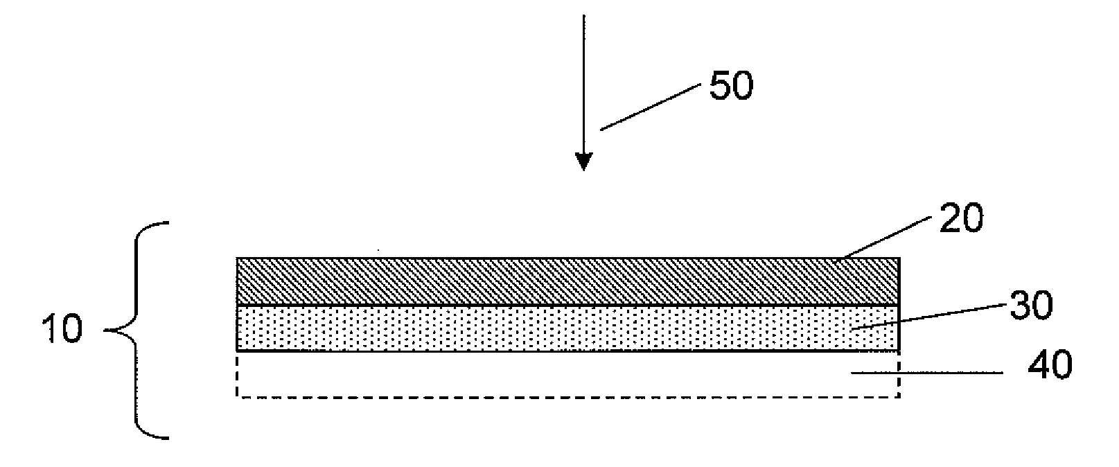
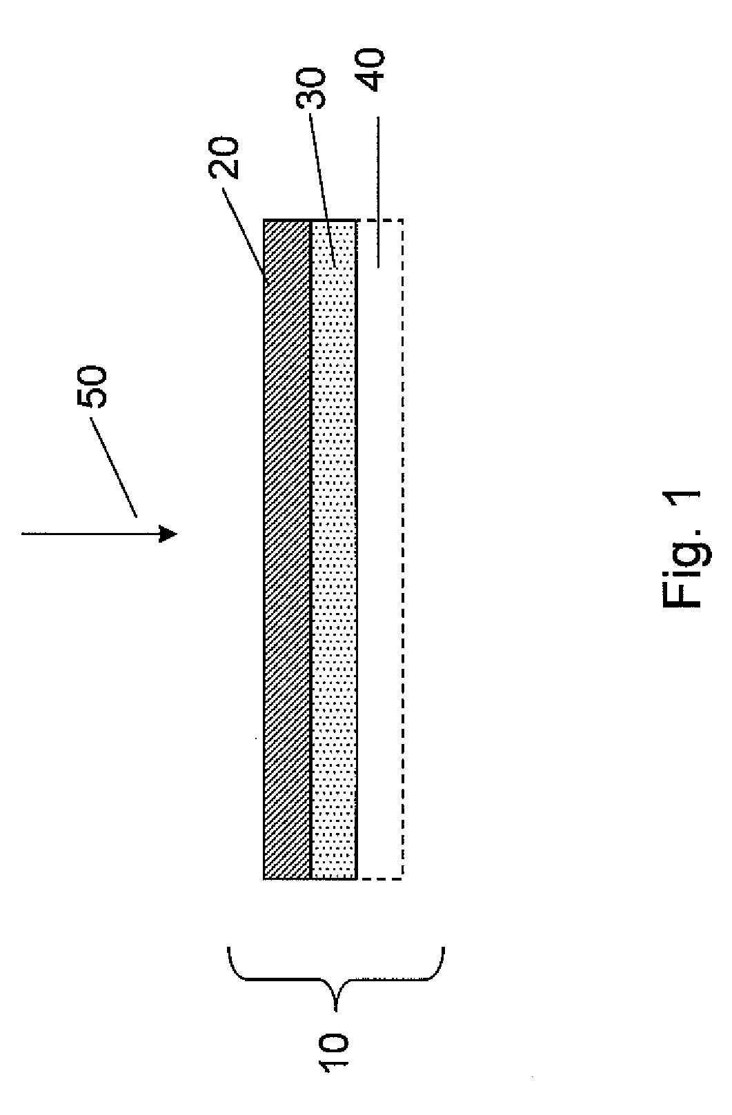
[0089]Two- and three-layered filter media were prepared according to the specifications listed in Table 1. The two-layered filter media (Samples 2A, 2B, and 3) included a first main filter layer (denoted top phase-main filter layer in Table 1) and a second main filter layer (bottom phase-main filter layer) adjacent the first layer.
[0090]The two-layered media was formed by a wet laid papermaking process. Briefly, for one layer, 250 gallons of water was added to a hydropulper, then sulfuric acid was added to bring the pH to approximately 3.0. Fibers were added to the mixture, and the fiber and water slurry was mixed for 4 minutes. The slurry was then pumped to a first holding chest with 900 gallons of additional water. For the second layer, this process was repeated with the fibers needed for the second layer, and the slurry was ...
example 2
[0093]This example describes the formation of several single- and multi-layered filter media and their characterization.
[0094]Table 2 includes various comparative samples having Beta(x)=1000, where x is about 4 to 4.5 microns. Comparative Sample 1A had a first (upstream) layer and a second (downstream) layer, the second layer having finer fibers than the first layer. The particular compositions of the first and second layers of Comparative Sample 1A are included in Table 4. The first and second layers were formed using the handsheet protocol described below. Comparative Samples 2-10 are commercial grades from Hollingsworth and Vose Company. As shown in Table 2, all of the comparative samples had absolute specific capacity at 10 μm values of less than 2.7.
TABLE 2Characteristics for various single- and multi-layered filter mediaAbsoluteResistanceResistanceSpecificBWBWRatioRatioBeta =Capacity @Sample(lbs / r)(g / m2)CFM(as is)(normalized)Capacity100010 μm(c)Comparative Sample 1A (2 layers,...
example 3
[0105]This example describes the characterization of several single- and multi-layered filter media.
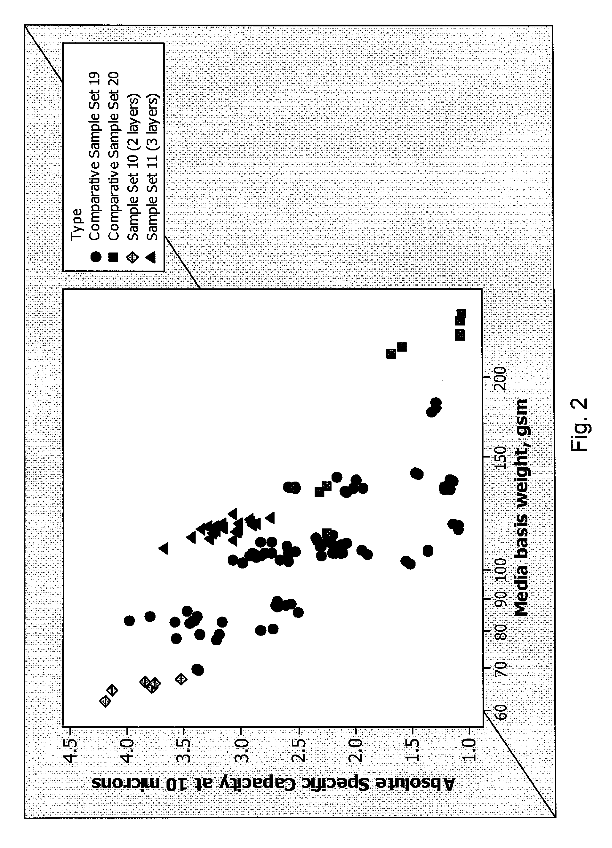
[0106]FIG. 2 shows the absolute specific capacity at 10 μm for various filter media plotted against the overall basis weight of the media. The basis weights were plotted on a log scale.
[0107]Comparative Sample Sets 19 and 20 are two- and three-layered media, respectively.
[0108]Sample Set 10 are two-layered media formed by the wet laid process described in Example 1. Sample Set 11 are three-layered media including a pre-filter layer, a first main filter layer, and a second main filter layer. The first and second main filter layers were fabricated using the wet laid process described in Example 1 to form a composite article, which was then collated to a pre-filter layer.
[0109]As shown in FIG. 2, Sample Set 10 (two-layered media) had higher absolute specific capacity at 10 μm values and lower basis weights than those of Comparative Sample Set 19 (two-layered media). For instance, the fil...
PUM
| Property | Measurement | Unit |
|---|---|---|
| Length | aaaaa | aaaaa |
| Diameter | aaaaa | aaaaa |
| Diameter | aaaaa | aaaaa |
Abstract
Description
Claims
Application Information
 - R&D
- Intellectual Property
- Life Sciences
- Materials
- Tech Scout
- Unparalleled Data Quality
- Higher Quality Content
- 60% Fewer Hallucinations
Browse by: Latest US Patents, China's latest patents, Technical Efficacy Thesaurus, Application Domain, Technology Topic, Popular Technical Reports.
© 2025 PatSnap. All rights reserved.Legal|Privacy policy|Modern Slavery Act Transparency Statement|Sitemap|About US| Contact US: help@patsnap.com


