Supercharge Your Innovation With Domain-Expert AI Agents!

Harvested Crop Chopper Remains And Distribution Arrangement For A Combine

Active Publication Date: 2010-09-30
DEERE & CO
View PDF15 Cites 10 Cited by
  • Summary
  • Abstract
  • Description
  • Claims
  • Application Information

AI Technical Summary

Benefits of technology

[0015]The harvested crop remains are then delivered to the outside on the basis of the centrifugal force and are concentrated on the basis of the surface curved in the forward direction and / or chamfered area of the impeller blade. The result is that the distribution of the harvested crop remains becomes less sensitive to any wind.
[0017]The axial dimensions of the axially outer area of the impeller blade of the outer area that is curved and / or angled in the direction of rotation (and If necessary, or the further area mentioned in the previous paragraph) increase in the radial direction of the impeller blades from inside to the outer radius in steps or smoothly. Thereby the harvested crop remains are concentrated gradually in the radial direction on their path from the inside to the outside up to their delivery, which reduced the sensitivity of the harvested crop remains to the wind.
[0023]When the harvested crop remains are conducted to the impeller blower in the axial direction an obvious solution is to arrange the axially outer area of the impeller blade that was angled towards the front and / or curved so that it faces the straw chopper. Thereby, not only the delivery of the harvested crop remains is improved, as described above, but also their reception.

Problems solved by technology

Thereby they provide a corresponding surface of attack to a side wind that may result in an undesired sideways drift of the harvested crop remains.
The impeller blades according to U.S. Pat. No. 6,343,896 B1 are not able to efficiently convey away harvested crop entering in the central region due to their geometry.

Method used


Image

  • Harvested Crop Chopper Remains And Distribution Arrangement For A Combine
  • Harvested Crop Chopper Remains And Distribution Arrangement For A Combine
  • Harvested Crop Chopper Remains And Distribution Arrangement For A Combine

Examples


Embodiment Construction

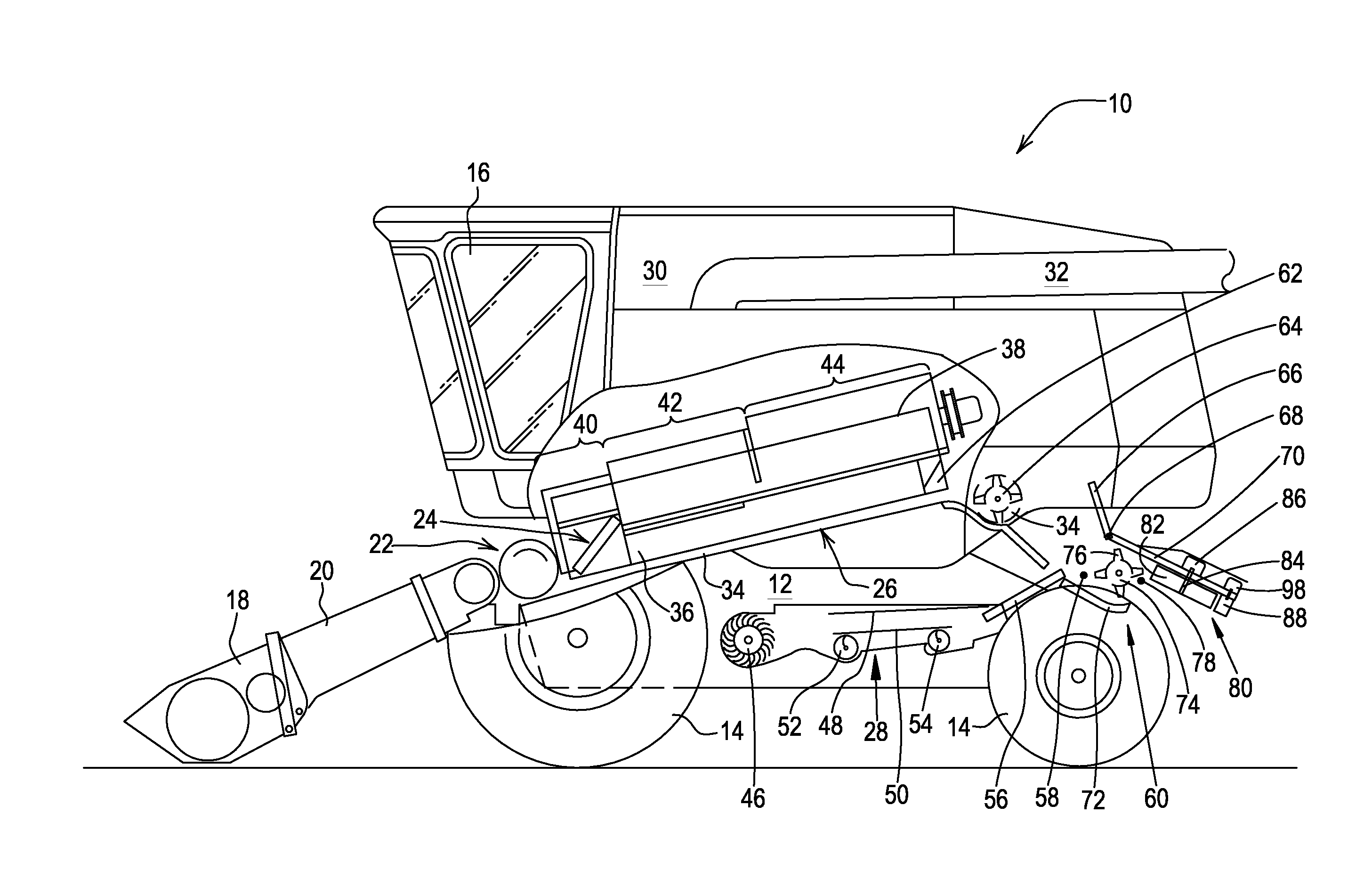
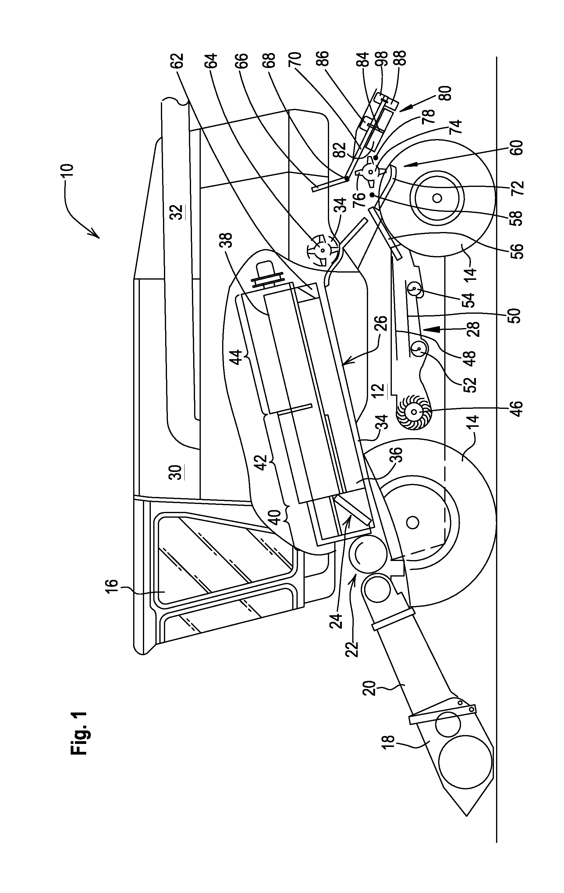
[0030]FIG. 1 shows an agricultural combine 10 with a chassis 12, with wheels 14 in contact with the ground that are fastened to the chassis 12 and are used for the propulsion of the combine 10 in the forward operating direction that extends to the left in FIG. 1. The operation of the combine 10 is controlled from the operator's cab 16. A cutter head 18 is used in order to harvest crop containing corn and to conduct it to a slope conveyor 20. The harvested crop is conducted by the slope conveyor 20 to a guide drum 22. The guide drum 22 conducts the harvested crop through an inlet transition section 24 to an axial harvested crop processing arrangement 26. In the following, directions such as front and rear refer to the forward operating direction of the combine 10 that extends to the left in FIG. 1.

[0031]The harvested crop processing arrangement 26 includes a rotor housing 34 and a rotor 36 arranged within it. The rotor 36 includes a hollow drum 38 to which crop processing elements ar...


PUM


Abstract

The invention concerns a harvested crop chopper remains-and-distribution arrangement for a combine (10) with a straw chopper (60) and an impeller blower (80) arranged downstream of the straw chopper (60), that includes at least one impeller blade (82) arranged to rotate in a direction of rotation about an axis (84) for the distribution across a field of the harvested crop remains provided by the straw chopper (60). An axially outer region (104, 106,114) of the impeller blade (82) leading in the direction of rotation is curved or angled in the direction of rotation. The axial dimension of the axially outer region (106) of the impeller blade (82) increases toward the outside in the radial direction. The impeller blade (82) is provided with a region (104) adjacent to the axial outer region (106) of the impeller blade, whose axial dimension decreases toward the outside in the radial direction and that extends in the radial direction and that is flat or is curved in a concave shape towards the front in the radial direction and is flatter than the outer region (106).

Description

FIELD OF THE INVENTION[0001]The invention concerns a harvested crop remains chopper-and-distribution arrangement with a straw chopper and an impeller blower arranged downstream of the straw chopper, that distributes the harvested crop remains delivered by the straw chopper across the field and includes at least one impeller paddle that rotates about an axis in a direction of rotation, where at least one area of the leading surface of the impeller paddle is curved and / or angled in the direction of rotation.BACKGROUND OF THE INVENTION[0002]Agricultural combines are large machines that harvest, thresh, separate and clean harvested crop, planted agriculturally that carries corn. The clean corn thus received is stored in a corn tank arranged on the combine. The threshed out straw is usually either chopped and distributed over the field across the width of the cutter head or conducted around the straw chopper and deposited in a swath across the field without being chopped, in order to be ...

Claims


Application Information

Patent Timeline
IPC IPC(8): A01F12/40
CPCA01D41/1243
Inventor LAUER, FRIEDRICHPOHLMANN, NORBERTWEICHOLDT, DIRKPRIESNITZ, RICOKLEIN, OLIVER
Owner DEERE & CO
Features
  • R&D
  • Intellectual Property
  • Life Sciences
  • Materials
  • Tech Scout
  • Unparalleled Data Quality
  • Higher Quality Content
  • 60% Fewer Hallucinations
Learn More