
System and Method for Signal Failure Detection in a Ring Bus System

a signal failure and ring bus technology, applied in the field of communication systems, can solve problems such as complex and expensive solutions, failure of the entire network, and inability to solve complex problems

Active Publication Date: 2010-09-30
SMSC EURO
View PDF15 Cites 23 Cited by
  • Summary
  • Abstract
  • Description
  • Claims
  • Application Information

AI Technical Summary

Benefits of technology

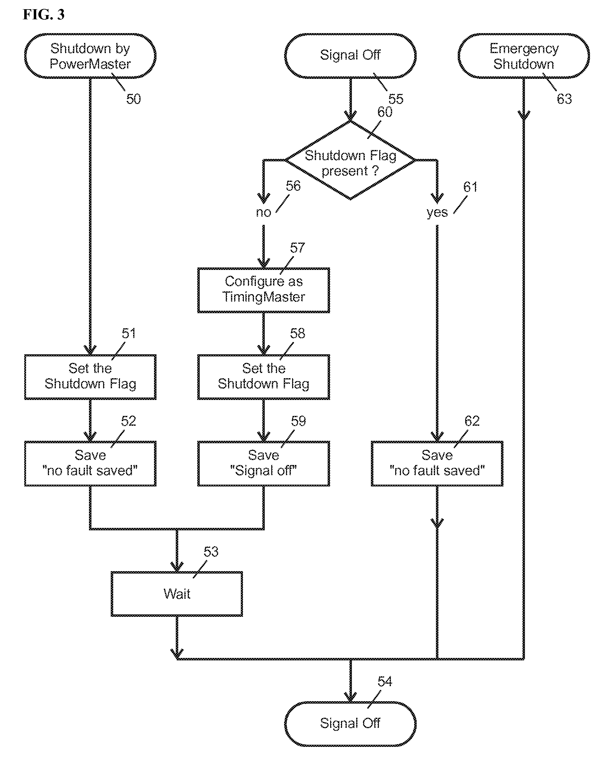
[0021]According to a further embodiment, in the case of an emergency shutdown, which may be caused by a low supply voltage or an over-temperature detected at the communication port, the signal at the output of the communication port is switched off immediately. This causes the succeeding communication port on the bus to detect a “signal off” state and to proceed as explained above by taking over the role as timing master, forwarding the shutdown flag to other network node's communication ports and saving its internal state of “sudden signal off.”

Problems solved by technology

In ring bus systems, failure of a single node leads to failure of the entire network.
This is not possible, if the controller itself or other hardware, which cannot be monitored by the controller, fails.
Furthermore the MAU requires one network port for each attached node, which makes this solution complex and expensive.

Method used


Image

  • System and Method for Signal Failure Detection in a Ring Bus System
  • System and Method for Signal Failure Detection in a Ring Bus System
  • System and Method for Signal Failure Detection in a Ring Bus System

Examples


Embodiment Construction

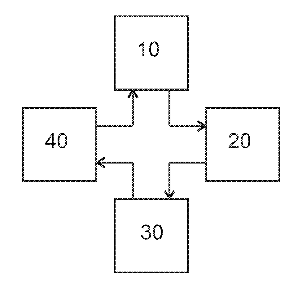
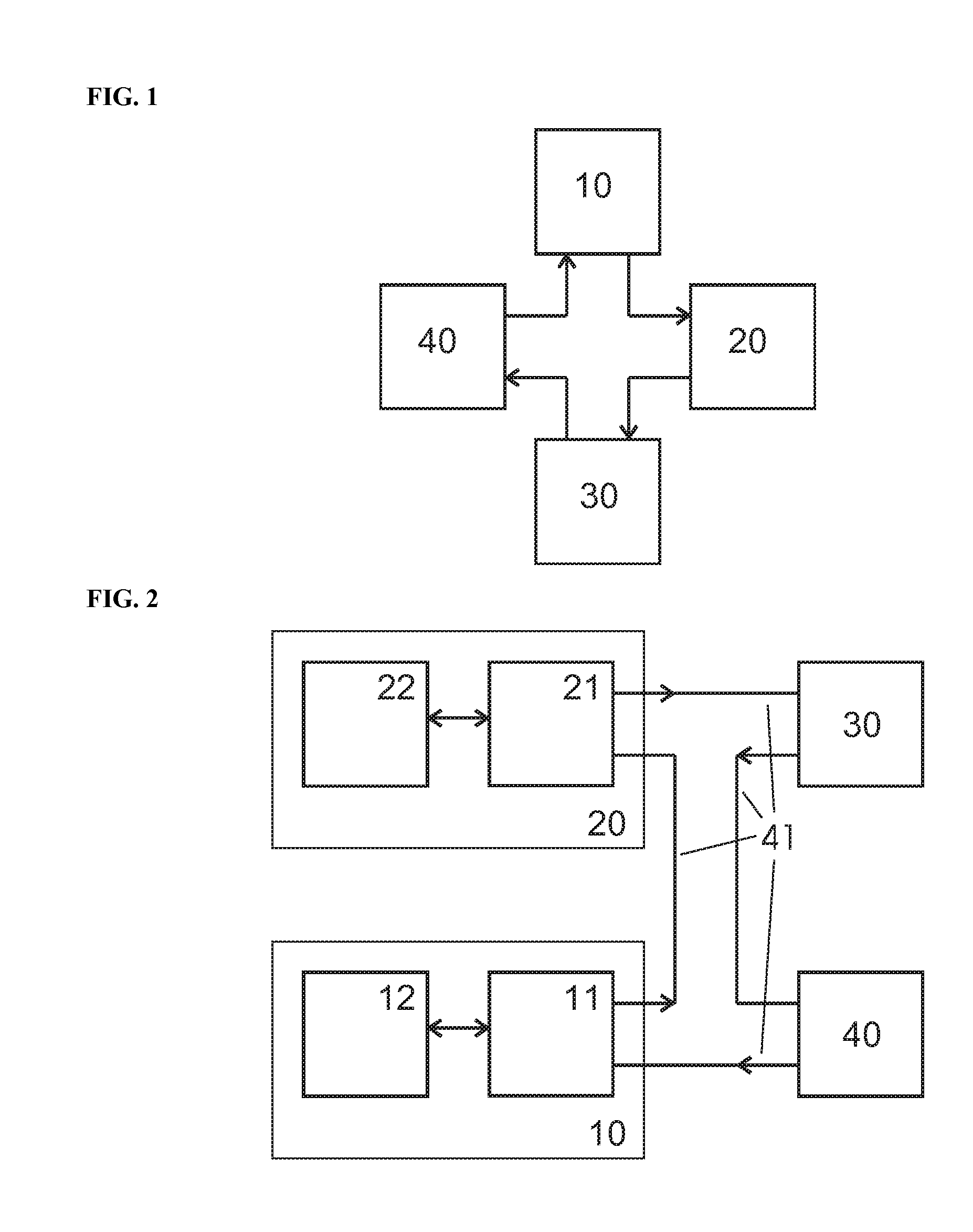
[0030]FIG. 1 shows a ring network comprising four network nodes. A first network node 10, a second network node 20, a third network node 30 and a fourth network node 40 are connected together to form a ring bus. Data is transferred in the direction of the arrows from first network node 10 to second network node 20 over third network node 30 and fourth network node 40 back to first network node 10.

[0031]FIG. 2 shows a ring bus as in FIG. 1, where the network nodes 10 and 20 are shown in more detail. The first and second network nodes 10 and 20 include communication ports, 11 and 21, respectively, which receive data from the network and send data over the network. Furthermore, the communication ports 11, 21 exchange data with the application 12, 22 of the network node. All network nodes are connected via the data bus lines 41.

[0032]In one embodiment, a communication port 11 in a bus node 10 receives data from a ring bus and transmits data onto the ring bus. During normal operation mod...


PUM


Abstract

A communication system, network node, and communication port architecture are provided for transporting data across a ring network. If a network node detects a signal failure, the communication port of the network node configures itself as timing master and communicates a shutdown command to the other network nodes. In addition, the communication port sets an internal flag signaling this “signal off” event. All other network nodes, which receive the shutdown flag, do not set this internal status, and instead, save a status of “no fault saved.” Accordingly, it can be easily determined where the loss of signal occurred.

Description

PRIORITY CLAIM[0001]This application is a continuation of pending International Application No. PCT / EP2008 / 063133 filed Oct. 1, 2008, which designates the United States and claims priority to European Patent Application No. EP 07117712.5 filed Oct. 2, 2007.BACKGROUND OF THE INVENTION[0002]1. Field of the Invention[0003]The invention relates to a communication system, ports of the communication system and a method for managing a communication system, all based on a ring network of two or more ports coupled preferably in daisy chain fashion to one another to allow communication.[0004]2. Description of Relevant Art[0005]The following descriptions and examples are given as background only.[0006]A communication system is generally known as a system that permits communication between nodes interconnected by a transmission line. Each node can transmit information and receive information across the transmission line. The communication system of interconnected nodes can be organized in vario...

Claims


Application Information

Patent Timeline
Patent Type & Authority Applications(United States)
IPC IPC(8): H04L12/26
CPCH04L12/40019H04L12/437H04L12/40032
Inventor KERBER, STEFANWILHELM, ROBERT
Owner SMSC EURO
Learn More