
System and Method for Receiving Antenna Measuring Signal and System for Measuring Antenna

Inactive Publication Date: 2010-09-23
ELECTRONICS & TELECOMM RES INST
View PDF5 Cites 8 Cited by
  • Summary
  • Abstract
  • Description
  • Claims
  • Application Information

AI Technical Summary

Benefits of technology

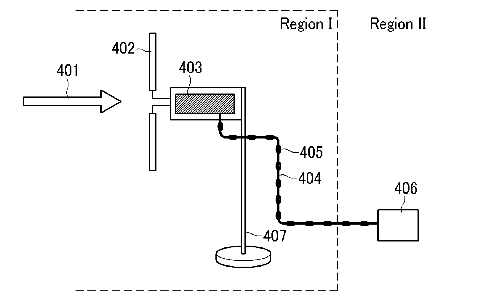
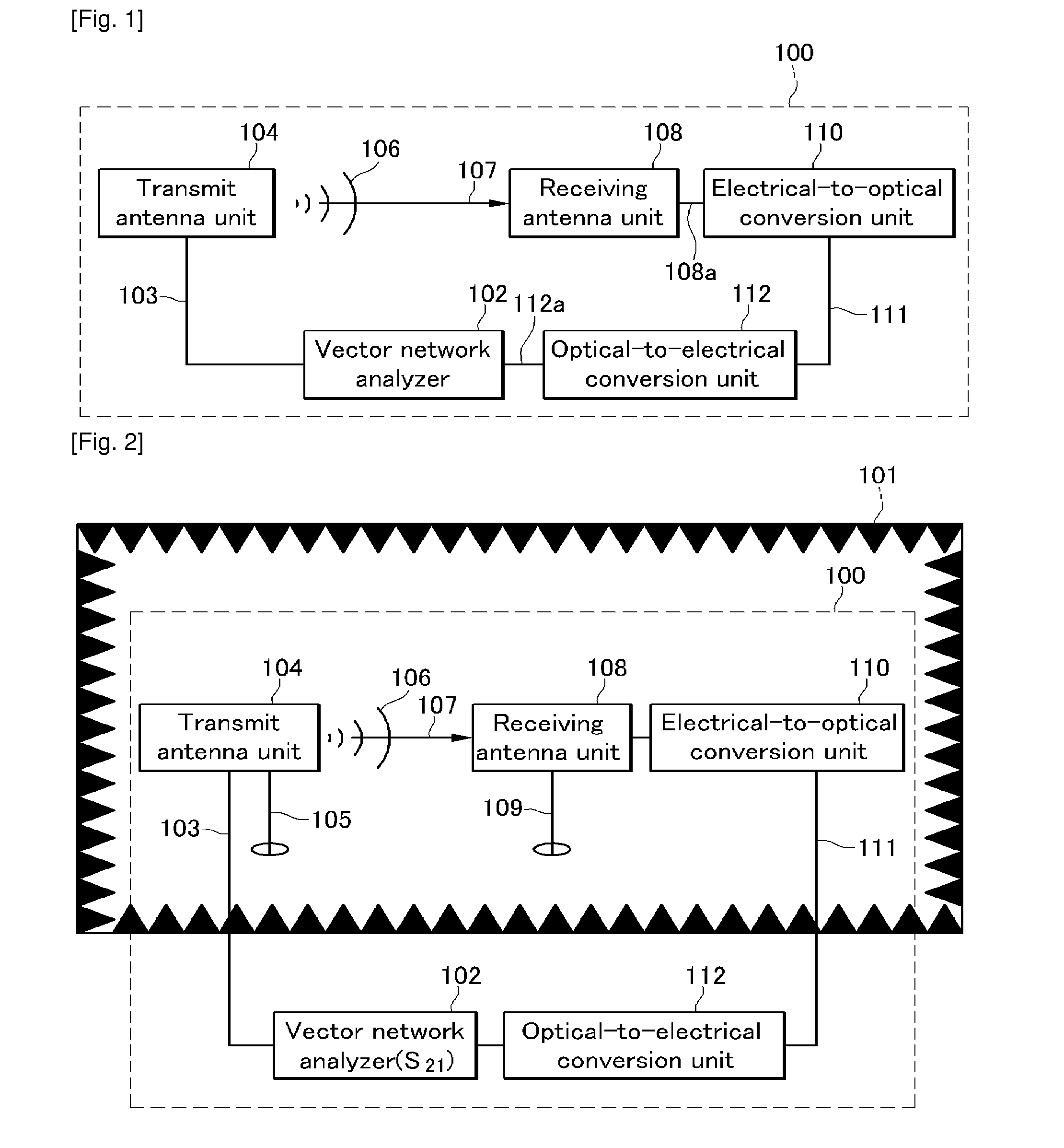
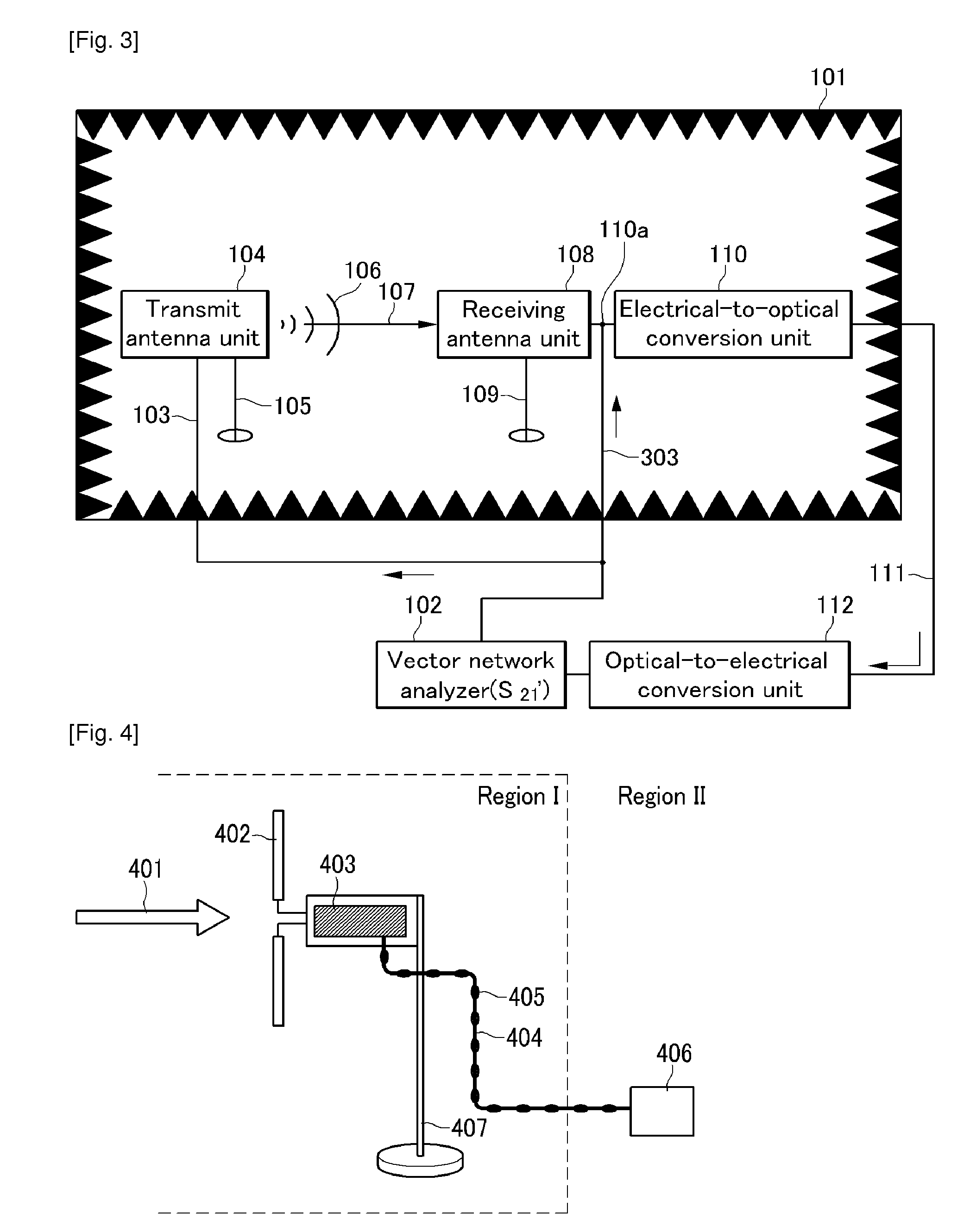
[0015]When using an apparatus and method for receiving an antenna measuring signal, and a system and method for measuring an antenna according to exemplary embodiments of the present invention, it is possible to remove the coupling effect of an RF cable of a receiving antenna side while measuring antenna characteristics, thereby minimizing a measurement error of the antenna.

Problems solved by technology

The above problems caused by the antenna cable are attributed to the fact that current is induced on the external shielding surface of the RF cable corresponding to a coaxial cable and the induced current forms the cable into a secondary radiator to thereby affect the level of signals received at the receiving antenna.
However, there is a disadvantage in that the scheme does not effectively eliminate the current induced in the RF cable in the gigahertz band.
However, the above scheme also has a disadvantage in that the scheme can be limitedly applicable only in a particular frequency band where the balloon effectively operates.

Method used


Image

  • System and Method for Receiving Antenna Measuring Signal and System for Measuring Antenna
  • System and Method for Receiving Antenna Measuring Signal and System for Measuring Antenna
  • System and Method for Receiving Antenna Measuring Signal and System for Measuring Antenna

Examples


Embodiment Construction

[0024]In the following detailed description, only certain exemplary embodiments of the present invention have been shown and described, simply by way of illustration. As those skilled in the art would realize, the described embodiments may be modified in various different ways, all without departing from the spirit or scope of the present invention. Accordingly, the drawings and description are to be regarded as illustrative in nature and not restrictive. Like reference numerals designate like elements throughout the specification.

[0025]Throughout this specification and the claims that follow, when it is described that an element is “coupled” to another element, the element may be “directly coupled” to the other element or “electrically coupled” to the other element through a third element.

[0026]In the specification, unless explicitly described to the contrary, the word “comprise” and variations such as “comprises” or “comprising” will be understood to imply the inclusion of stated ...


PUM


Abstract

The present invention relates to an apparatus and method for receiving an antenna measuring signal, and a system of measuring an antenna. In particular, the present invention relates to an apparatus and method for receiving an antenna measuring signal that can remove a measurement error caused by motion of an antenna cable, and a system for measuring an antenna. According to the apparatus and method for receiving an antenna measuring signal and the system and method for measuring an antenna according to the present invention, it is possible to remove a coupling effect of an RF cable of a receiving antenna side while measuring antenna characteristics, thereby minimizing a measurement error of the antenna.

Description

TECHNICAL FIELD[0001]The present invention relates to an apparatus and method for receiving an antenna measuring signal, and a system for measuring an antenna. Particularly, the present invention relates to an apparatus and method for receiving an antenna measuring signal that can remove a measurement error caused by motion of an antenna cable, and a system for measuring an antenna.[0002]This work was supported by the IT R&D program of MIC / IITA [2007-P-010-38, Development of Broadband RF Antenna Measuring Technology Standard].BACKGROUND ART[0003]An antenna that is an essential element of wireless communication has been widely used in every field ranging from all kinds of enhanced technologies using radio waves such as mobile communication, radar, electronic countermeasures (ECM) / electronic counter-countermeasures (ECCM), telemetry, remote searching, electromagnetic interference (EMI) / electromagnetic compatibility (EMC) measurement, broadcasting, radio astronomy, navigation, etc., to...

Claims


Application Information

Patent Timeline
IPC IPC(8): G01R29/08
CPCH01Q3/267H01Q1/24
Inventor CHO, IN KUIYUN, JE HOONOH, SOON-SOOMOON, JUNG ICKKIM, JOUNG MYOUNJEON, SOON IKKIM, CHANG-JOO
Owner ELECTRONICS & TELECOMM RES INST
Learn More