Metal strip resistor for mitigating effects of thermal emf

a technology of resistors and metal strips, applied in the field of resistors, can solve the problems of significant measurement errors, increased cost, and resistors susceptible to adverse effects of thermal emf, and achieve the effect of reducing the effect of thermally induced voltages

Inactive Publication Date: 2010-09-23
VISHAY DALE ELECTRONICS INC
View PDF14 Cites 13 Cited by
  • Summary
  • Abstract
  • Description
  • Claims
  • Application Information

AI Technical Summary

Benefits of technology

[0008]According to one embodiment a metal strip resistor is provided. The metal strip resistor includes a resistor body having at least one resistive element formed from a strip of a resistive metal material, (such as Evanohm, Manganin, or others), and a first termination electrically connected to the resistive element to form a first junction and a second termination electrically connected to the resistive element to form a second junction; the first termination and the second termination being formed from strips of highly electrically conductive metal material, such as copper or others, with high electrical conductivity. Prior art metal strip resistors are described in U.S. Pat. No. 5,604,477 (Rainer et al.). The resistive element, the first termination, and the second termination are arranged to assist in mitigating effects of thermally induced voltages between the first junction and the second junction. The resistor body may include a fold between a first portion of the resistor body and a second portion of the resistor body. A thermoconductive and electrically non-conductive material may be used to thermally connect the first portion of the resistor body to the second portion of the resistor body and assist in reducing the temperature differential between the first junction and the second junction to thereby mitigate the effects of the thermally induced voltages between the first junction and the second junction.
[0009]According to another embodiment, a metal strip resistor is provided. The metal strip resistor includes a resistor body having a resistive element formed from a strip of a resistive metal material and a first termination joined to the resistive element to form a first junction and a second termination joined to the resistive element to form a second junction; the first termination and the second termination being formed from strips of highly electrically conductive metal material. The resistor body is folded onto itself and mating surfaces are bonded with a thermally conductive and electrically non-conductive adhesive to thereby equalize the temperature between the two sides of the resistor body thus mitigating effects of thermally induced voltages between the first junction and the second junction.
[0011]According to another embodiment, a method of manufacturing a metal strip resistor includes joining a resistive metal material with an electrically conductive material to form a resistor body with a plurality of junctions between the resistive metal material and the electrically conductive material, folding the resistor body, and bonding the resistor body on one side of the fold to the resistor body on an opposite side of the fold with a thermoconductive and electrically non-conductive adhesive to thereby form a metal strip resistor configured for mitigating effects of thermally induced voltages.

Problems solved by technology

A resistor may have a metal resistive element connected between copper terminals, thereby providing two junctions and making the resistor susceptible to adverse effects of thermal EMF.
In cases where the current is low, the signal voltage generated across the resistor is also very small and any voltage caused by thermal EMF can cause a significant measurement error.
In some cases this presents other challenges such as increased cost, an increase in bulk resistivity that creates a resistor geometry that is costly to manufacture, or sacrifices other electrical characteristics such as TCR (temperature coefficient of resistance).
Such an approach adds material cost, complexity to the assembly, and manufacturing cost in terms of assembly steps and equipment.

Method used


Image

  • Metal strip resistor for mitigating effects of thermal emf
  • Metal strip resistor for mitigating effects of thermal emf
  • Metal strip resistor for mitigating effects of thermal emf

Examples


Embodiment Construction

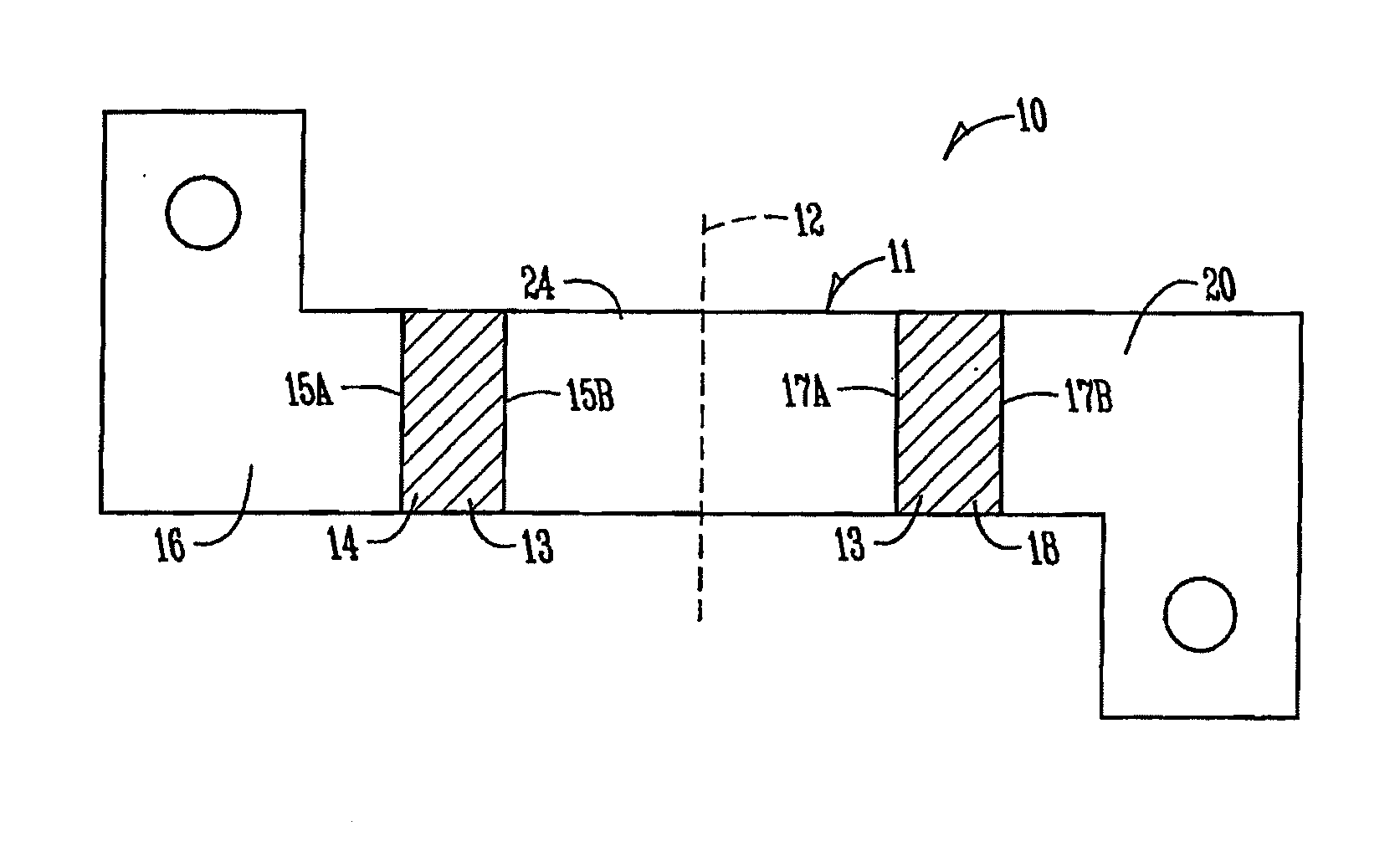
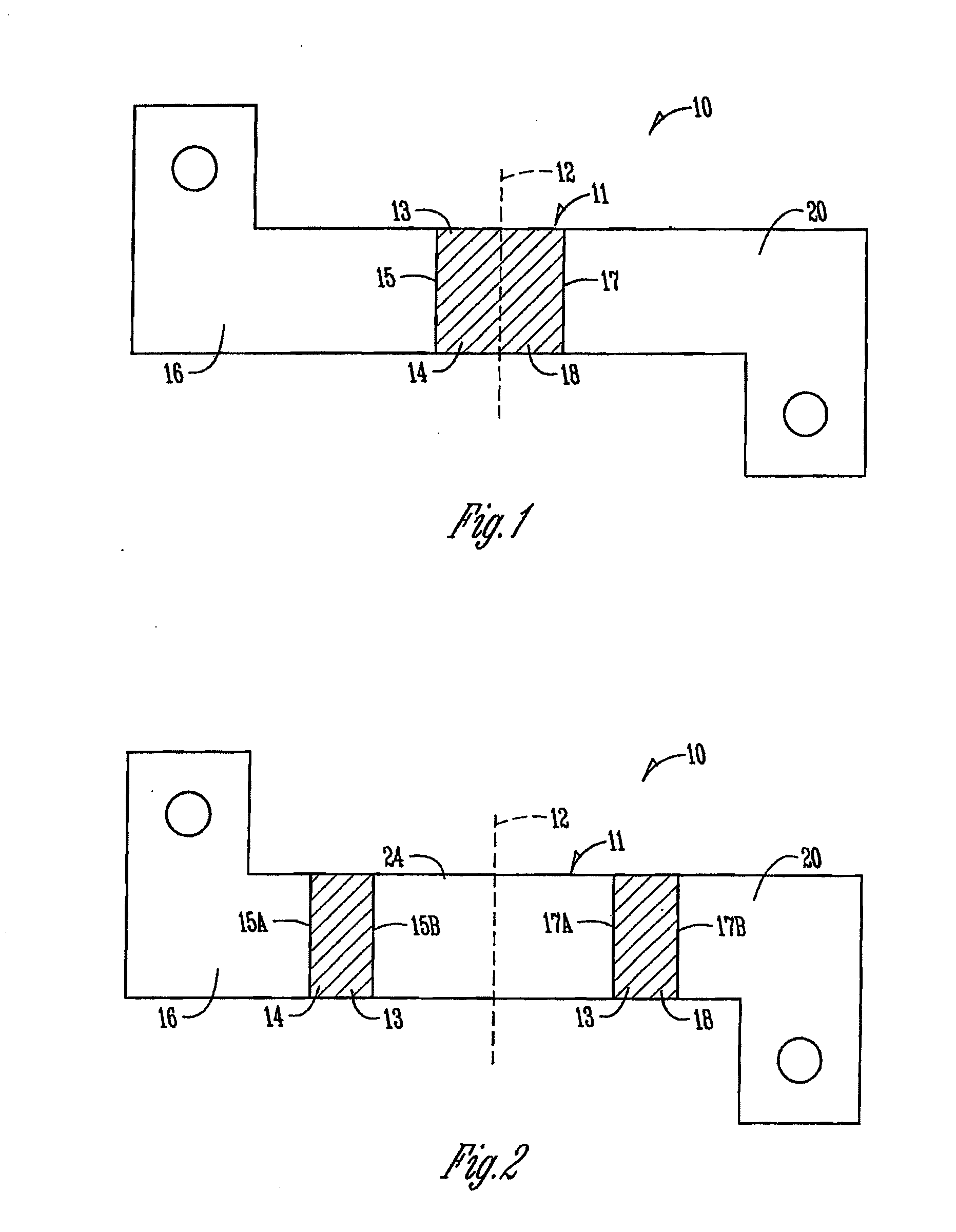
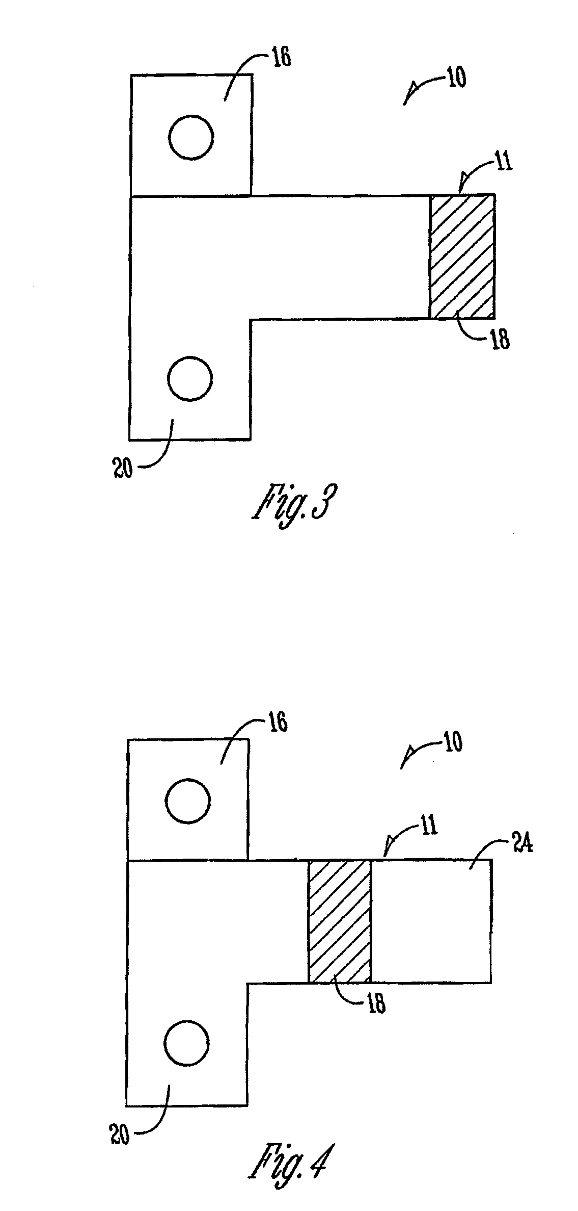
[0023]The embodiments disclosed herein provide a resistor for mitigating effects of thermal electromotive force (EMF). This allows the use of any number of types of metal resistance alloy regardless of thermal EMF and negates any termination to termination temperature differential. The embodiments disclosed herein achieve desirable results by using appropriate resistor geometries, metal forming, and / or heat transfer materials.

[0024]Note that, rather than change a resistor's resistive element material and / or termination material, or add compensation circuitry to offset the thermal EMF of a specific set of resistor metal alloys, the embodiments disclosed herein provide for using a geometry that brings both metallic junctions to the same temperature. In overcoming the problem in this way the embodiments disclosed herein function regardless of the metal alloys used and their specific thermal EMF characteristics. Thus, the embodiments disclosed herein are not limited to particular types ...


PUM


Abstract

A metal strip resistor includes a resistor body having a resistive element formed from a strip of an electrically resistive metal material and a first termination electrically connected to the resistive element to form a first junction and a second termination electrically connected to the resistive element to form a second junction, the first termination and the second termination formed from strips of electrically conductive metal material. The resistive element, the first termination, and the second termination being arranged mitigate thermally induced voltages between the first junction and the second junction.

Description

CROSS REFERENCE TO RELATED APPLICATIONS[0001]This application claims the benefit of U.S. Provisional Application Ser. No. 61 / 161,636 filed on Mar. 19, 2009 and U.S. Provisional Application Ser. No. 61 / 169,377 filed on Apr. 15, 2009, both of which are incorporated by reference as if fully set forth.FIELD OF THE INVENTION[0002]The present invention relates to resistors. More specifically, the present invention relates to metal strip resistors configured to assist in mitigating the effects of thermal EMF.BACKGROUND OF THE INVENTION[0003]Thermal electromotive force (EMF) is a voltage that is generated when two dissimilar metals are joined together. When there are two of these junctions that are of opposite polarity and the temperature of the junctions are equal, there is no net voltage. When one of the junctions is at a different temperature than the other, a net voltage difference can be detected. A resistor may have a metal resistive element connected between copper terminals, thereby...

Claims


Application Information

Patent Timeline
IPC IPC(8): H01C1/012H01C17/00
CPCH01C1/084Y10T29/49082H01C3/06
Inventor BRACKHAN, DOUGSMITH, CLARK L.VEIK, THOMAS L.
Owner VISHAY DALE ELECTRONICS INC
Why Eureka
Try Eureka