Cellulose nanofiber production method of same and cellulose nanofiber dispersion
a technology of cellulose nanofibers and production methods, which is applied in the direction of cellulose pulp after-treatment modification, transportation and packaging, yarn, etc., can solve the problem of inability to easily disperse into individual nanofibers, and achieve the effects of superior transparency or whiteness, high degree of polymerization, and superior strength
- Summary
- Abstract
- Description
- Claims
- Application Information
AI Technical Summary
Benefits of technology
Problems solved by technology
Method used
Image
Examples
example 1
[0117]In this example, an explanation is provided of the results of examining reaction pH, reaction time and reaction temperature.
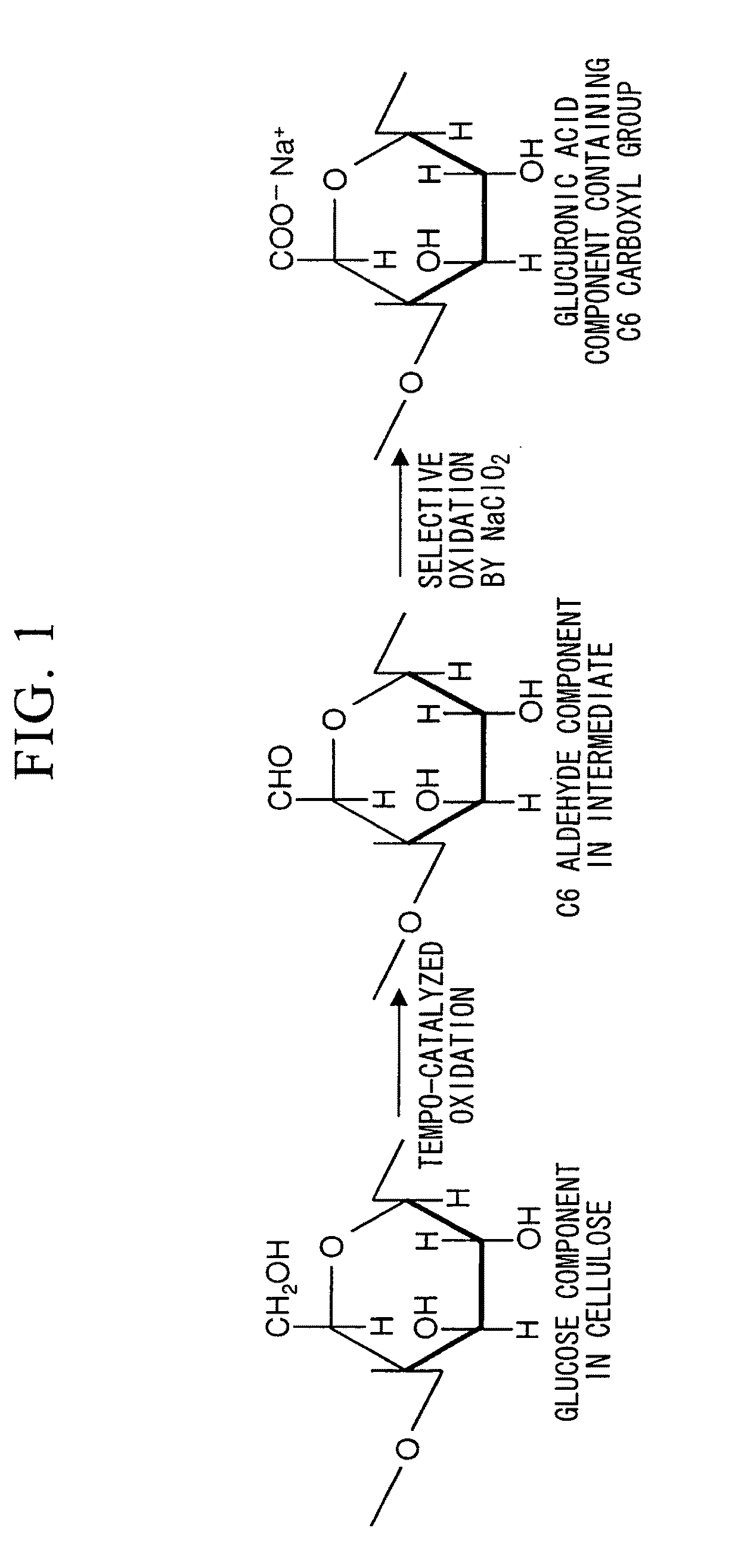
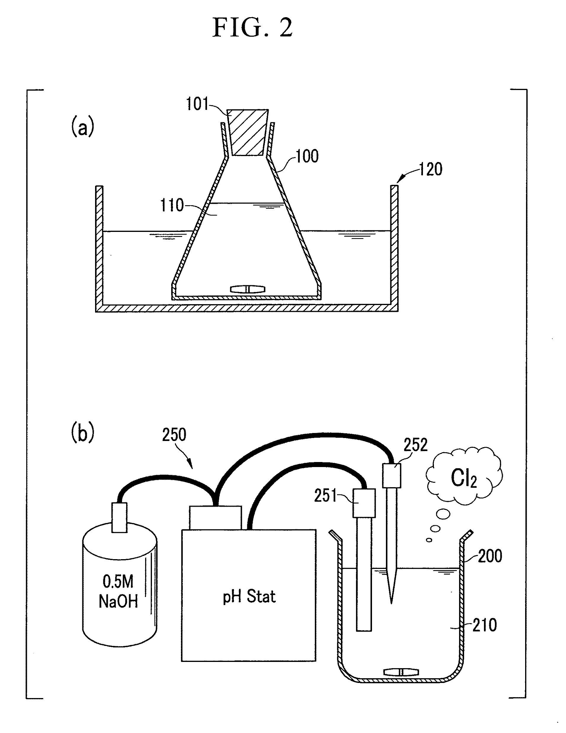
[0118]Wood cellulose (1 g) was respectively dispersed in 0.1 M aqueous acetic acid adjusted to pH 3.5, 0.1 M acetate buffer adjusted to pH 4.8, and 0.1 M phosphate buffer adjusted to pH 6.8, followed by the addition of 0.1 mmol (0.0156 g) of TEMPO and 10 mmol of sodium chlorite (1.13 g of commercially available 80% sodium chlorite) to each solution in an Erlenmeyer flask, sealing the flask and stirring with a magnetic stirrer until the native cellulose was adequately dispersed.
[0119]Subsequently, 2.5 mL of an aqueous sodium hypochlorite solution having a concentration of 0.2 M were added to the reaction solution followed immediately by resealing the flask. The amount of sodium hypochlorite added at this time was 0.5 mmol based on 1 g of native cellulose.
[0120]Subsequently, the sealed reaction vessel was stirred for a prescribed amount of time (2 to 72 hou...
example 2
[0132]In this example, an explanation is provided of the results of examining the amount of sodium hypochlorite added to the reaction solution.
[0133]In this example, oxidized cellulose was prepared while varying the amount of sodium hypochlorite added to the reaction solution within the range of 0 to 1.0 mmol / g. Other conditions of the reaction solution were the same as in Example 1.
[0134]The results of defibration treatment and carboxyl group measurement in the resulting oxidized cellulose carried out in the same manner as Example 1 are shown in Table 2.
TABLE 2Amt. of sodiumReactionAmt. of carboxyl groupshypochlorite addedtimeTemp.in oxidized cellulose(mmol / g)pH(hr)(° C.)(mmol / g)06.82600.120.36.82600.410.56.82600.481.06.82600.570.36.82400.360.36.86400.430.36.818400.500.56.82400.410.56.86400.580.56.822400.641.06.624600.67
[0135]Based on the results of Table 2, the amount of carboxyl groups in the oxidized cellulose increases with increase in the amount of sodium hypochlorite added. I...
example 3
[0136]In this example, an explanation is provided of the results of examining the type of catalyst added to the reaction solution.
[0137]In this example, oxidized cellulose was prepared respectively using TEMPO and 4-acetoamide-TEMPO for the oxidation catalyst added to the reaction solution. FIG. 4 shows the chemical structures of these oxidation catalysts. Other conditions of the reaction solution were the same as in Example 1.
[0138]The results of carboxyl group measurement in the resulting oxidized cellulose carried out in the same manner as Example 1 are shown in Table 3.
TABLE 3ReactionAmt. of carboxyltimeTemp.groups in oxidizedCatalystpH(hr)(° C.)cellulose (mmol / g)4-acetoamide-TEMPO5.022400.38TEMPO5.022400.304-acetoamide-TEMPO6.822400.68TEMPO6.822400.64
[0139]Based on the results of Table 3, improvement of efficiency of the oxidation reaction was observed as a result of using 4-acetoamide-TEMPO. However, the effect of pH on the reaction system was considerably greater. Thus, contr...
PUM
| Property | Measurement | Unit |
|---|---|---|
| number average fiber diameter | aaaaa | aaaaa |
| number average fiber diameter | aaaaa | aaaaa |
| number average fiber diameter | aaaaa | aaaaa |
Abstract
Description
Claims
Application Information
 - R&D
- Intellectual Property
- Life Sciences
- Materials
- Tech Scout
- Unparalleled Data Quality
- Higher Quality Content
- 60% Fewer Hallucinations
Browse by: Latest US Patents, China's latest patents, Technical Efficacy Thesaurus, Application Domain, Technology Topic, Popular Technical Reports.
© 2025 PatSnap. All rights reserved.Legal|Privacy policy|Modern Slavery Act Transparency Statement|Sitemap|About US| Contact US: help@patsnap.com


