
Image Forming Apparatus And Mist Recovery Method

Inactive Publication Date: 2010-09-16
FUJIFILM CORP
View PDF13 Cites 31 Cited by
  • Summary
  • Abstract
  • Description
  • Claims
  • Application Information

AI Technical Summary

Benefits of technology

[0020]The present invention has been contrived in view of these circumstances, an object thereof being to provide an image forming apparatus and a mist recovery method whereby mist-like droplets produced during ejection of liquid are prevented from adhering to the liquid ejection face, number of maintenance operations of the apparatus is reduced, and continuous operation over a long period of time becomes possible.

Problems solved by technology

If evaporation of the functional material contained in the ink can be ignored, then the size of the mist particles is approximately 0.5 μm to 10 μm, and it is particularly difficult to suppress the occurrence of the mist particles of around 1 μm in size.
The mist floats about inside the image forming apparatus, soils the interior of the image forming apparatus, and in particular, if the mist adheres to the nozzle plate (ejection face) of the ink ejection head, then it may give rise to ejection abnormalities.
Furthermore, if the mist adheres to a detector, such as an encoder, then this gives rise to conveyance abnormalities of the recording medium and can lead to printing abnormalities caused by the conveyance abnormalities.
These printing abnormalities have an adverse effect on image formation.
If a large volume of the satellite droplets 402 overflows into the nozzle 451, then all or a portion of the nozzle 451 is covered and there is a very high possibility of this giving rise to ejection abnormalities.
In the mist recovery by means of electrostatic attraction described in Japanese Patent Application Publication No. 2005-349799, it is difficult to collect the mist in a reliable manner.
Moreover, in order to remove the mist in the vicinity of the nozzle plate, it is necessary to apply a strong electric field or a strong attraction force, and the strong electric field or attraction force may have adverse effects on the linearity of flight of the ejected ink droplets.

Method used


Image

  • Image Forming Apparatus And Mist Recovery Method
  • Image Forming Apparatus And Mist Recovery Method
  • Image Forming Apparatus And Mist Recovery Method

Examples


Embodiment Construction

Entire Configuration of Inkjet Recording Apparatus

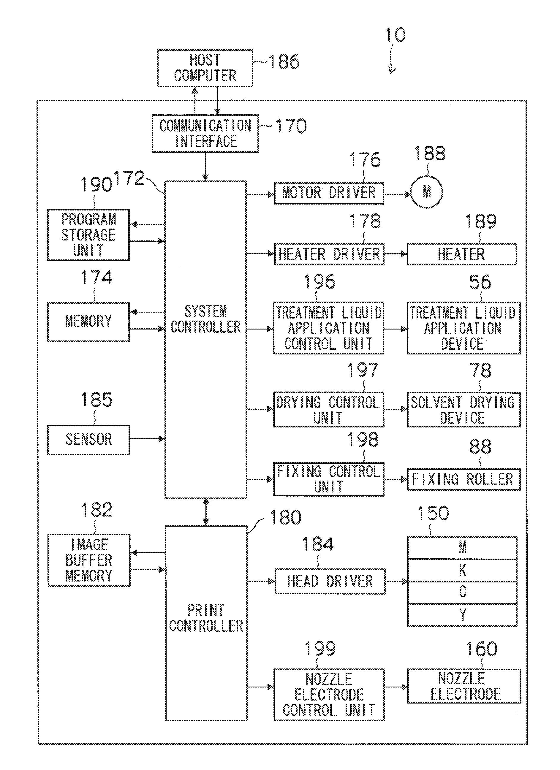
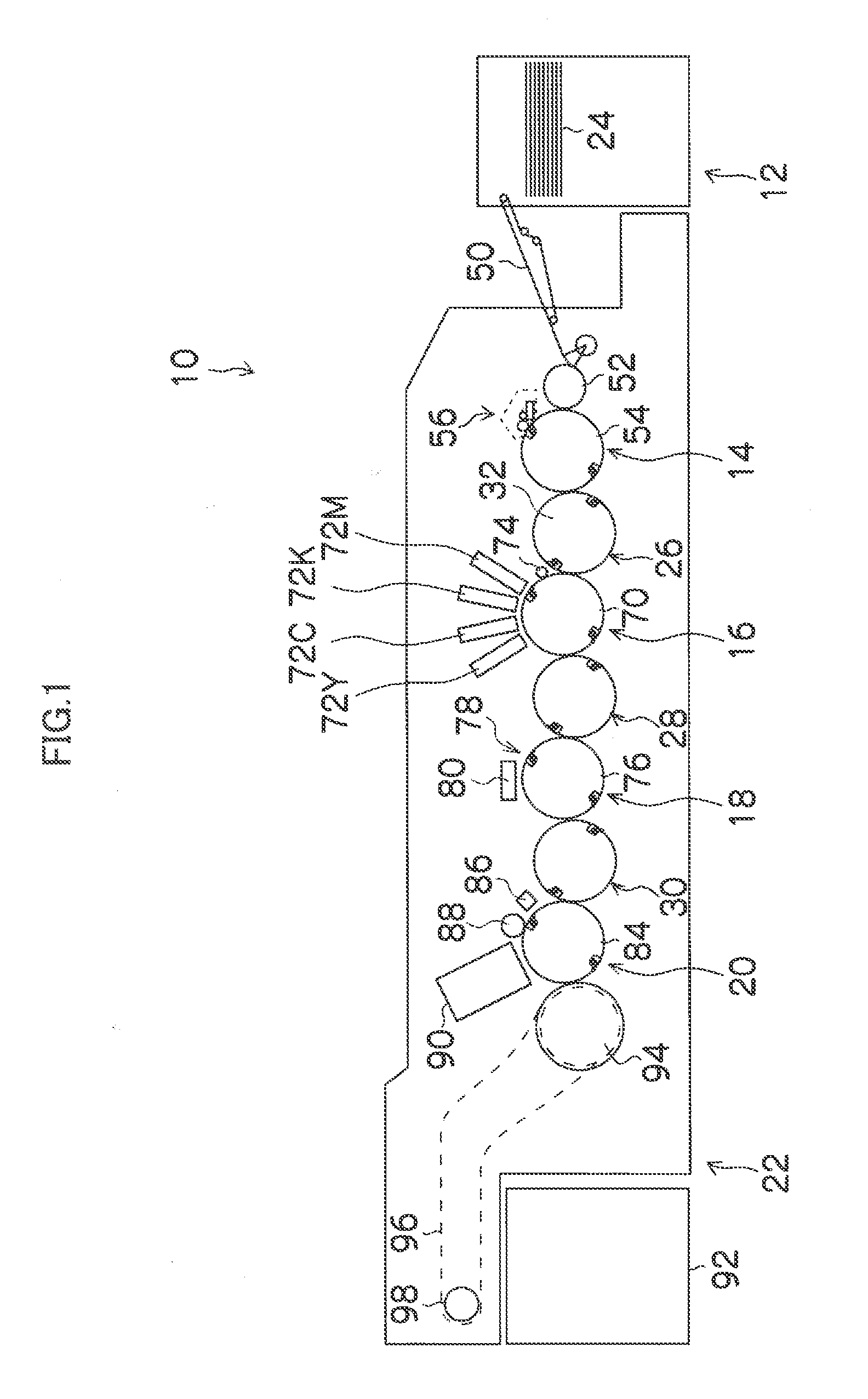
[0035]First, an inkjet recording apparatus of an on-demand type will be described as an embodiment of an image forming apparatus according to the present invention.

[0036]FIG. 1 is a structural diagram illustrating the entire configuration of an inkjet recording apparatus 10 according to an embodiment of the present invention. The inkjet recording apparatus 10 shown in the drawing is an recording apparatus in a two-liquid aggregating system of forming an image on a recording surface of a recording medium 24 by using ink (an aqueous ink) and a treatment liquid (aggregation treatment liquid). The inkjet recording apparatus 10 includes a paper feed unit 12, a treatment liquid application unit 14, an image formation unit 16, a drying unit 18, a fixing unit 20, and a discharge unit 22 as the main components. A recording medium 24 (paper sheets) is stacked in the paper feed unit 12, and the recording medium 24 is fed from the paper feed uni...


PUM


Abstract

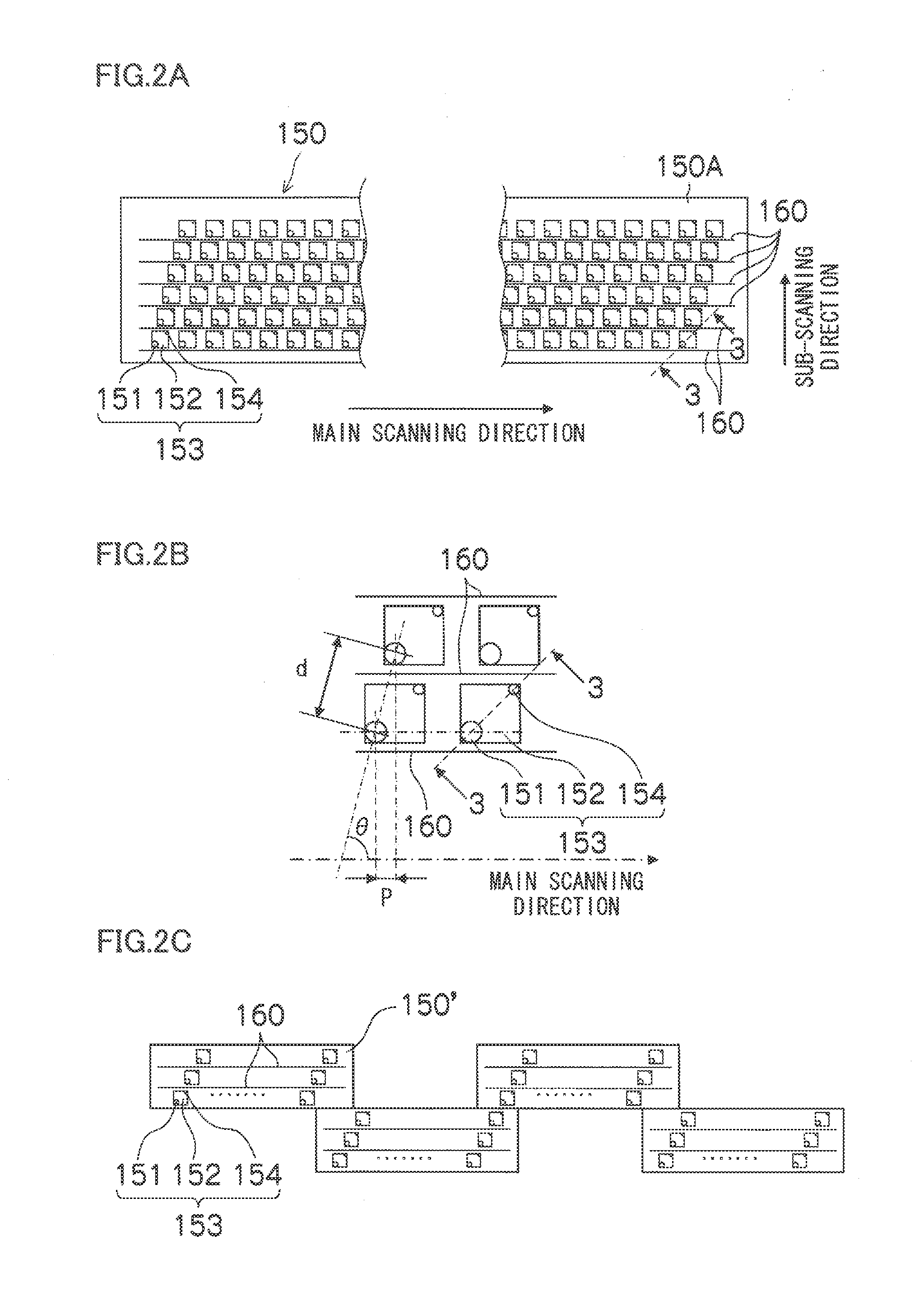
The image forming apparatus includes: an inkjet head of an on-demand ejection type having a nozzle plate in which a nozzle electrode is arranged in a vicinity of a nozzle through which liquid is ejected; and a voltage application device which makes a polarity of the nozzle electrode one of positive and negative in accordance with a start of an ejection operation of the liquid, and then switches the polarity of the nozzle electrode to an opposite polarity to the one of positive and negative in accordance with a timing of ejecting the liquid through the nozzle.

Description

BACKGROUND OF THE INVENTION[0001]1. Field of the Invention[0002]The present invention relates to an image forming apparatus and a mist recovery method, and more particularly to technology for preventing the adherence, to a liquid ejection face, of droplets in the form of a mist generated when the liquid is ejected from an inkjet head.[0003]2. Description of the Related Art[0004]An image forming apparatus which forms an image by ejecting and depositing ink or a functional material onto a recording medium using an inkjet head is excellent from an environmental viewpoint and enables high-speed recording on a variety of recording media, as well as producing an image of high definition while avoiding bleeding of ink, and the like, and therefore is used as a generic image forming apparatus in a variety of fields.[0005]In the case of ink ejection by an inkjet method, together with the occurrence of a main droplet, satellite droplets which are much smaller than the main droplet or a mist wh...

Claims


Application Information

Patent Timeline
IPC IPC(8): B41J29/38B41J2/165
CPCB41J2/14233B41J2202/20B41J2002/14459B41J2/155
Inventor HIRATO, KATSUYUKI
Owner FUJIFILM CORP
Learn More