
Magnetic field detector having a variable threshold

Active Publication Date: 2010-09-16
ALLEGRO MICROSYSTEMS INC
View PDF27 Cites 29 Cited by
  • Summary
  • Abstract
  • Description
  • Claims
  • Application Information

AI Technical Summary

Benefits of technology

[0015]With this arrangement, the threshold offset amount of the peak detector is advantageously tailored to the peak-to-peak signal level of the magnetic field signal so that in larger airgap installations, where the peak-to-peak magnetic field signal level is smaller, the threshold offset amount is likewise smaller to ensure that the detector output signal switches as appropriate in response to the passing magnetic article; whereas in smaller airgap installations, where the peak-to-peak magnetic field signal is larger, the threshold offset amount is larger to prevent undesirable output signal switching as a result of magnetic field signal overshoot. And unlike conventional arrangements that base the threshold offset amount on the absolute value of the peak magnetic field signal level to prevent switching on magnetic overshoot at close airgap, use of the peak-to-peak magnetic field signal level advantageously permits the use of a differential or single-ended sensor. Additionally, the threshold offset amount is further advantageously tailored to the speed of rotation of the magnetic article so that the threshold offset amount, which initially at power up is set a larger amount, is not allowed to be adjusted to the smaller threshold offset amount until the magnetic article rotates at a predetermined speed. In this way, undesirable output signal switching due to target vibration at power up is avoided. Furthermore, the optimization of the threshold offset amount to rotation speed and magnetic field signal conditions occurs continuously during detector operation, rather than just at startup, and therefore provides the above-described advantages even in response to changing conditions.

Problems solved by technology

Detection accuracy can be adversely affected by variations in the magnetic field signal that are attributable to factors other than the passing magnetic article.
It can be challenging to choose a threshold signal level that is suitable for both small and large airgap installations.

Method used


Image

  • Magnetic field detector having a variable threshold
  • Magnetic field detector having a variable threshold
  • Magnetic field detector having a variable threshold

Examples


Embodiment Construction

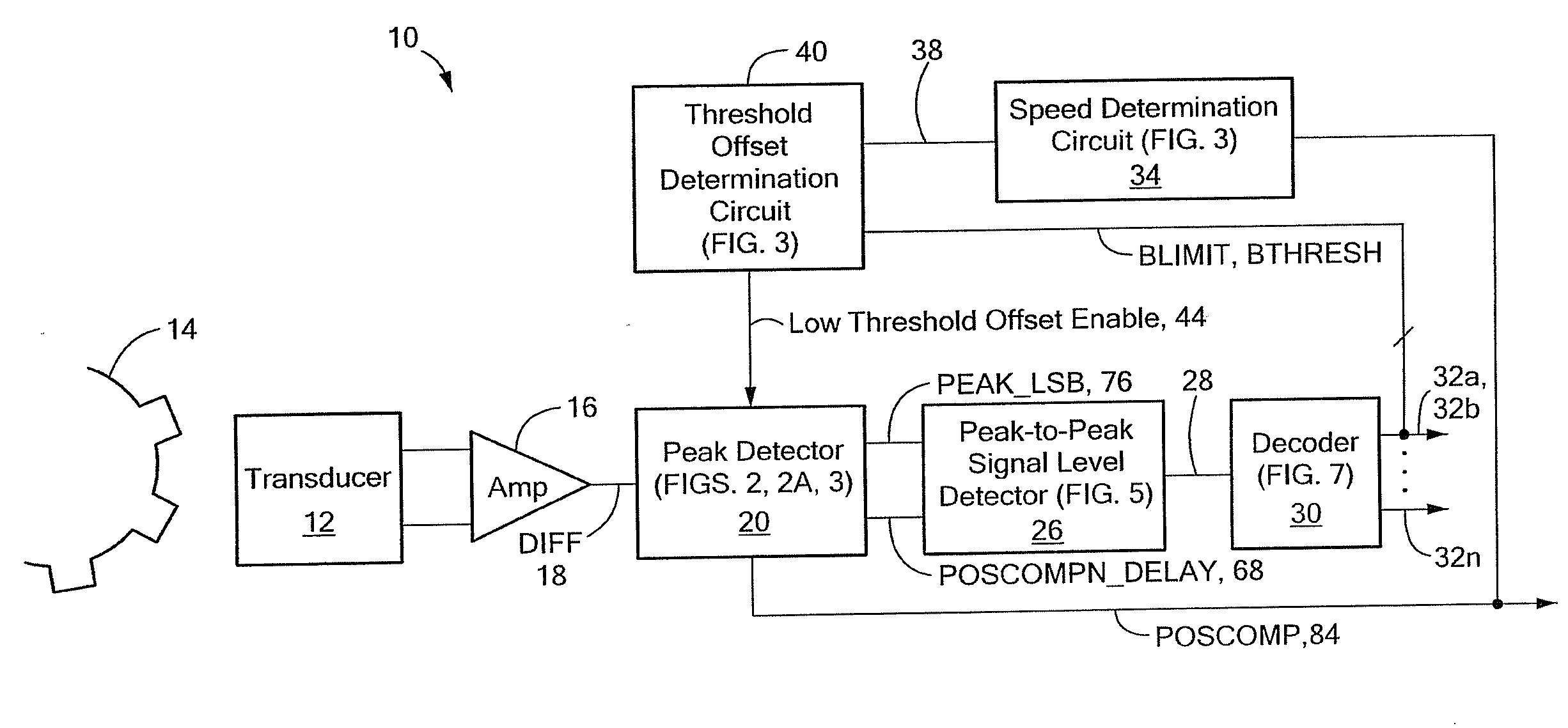
[0026]Referring to FIG. 1, a magnetic field detector 10 with a dynamically variable threshold feature includes a magnetic field transducer 12, a peak detector 20, a peak-to-peak signal level detector 26, a speed determination circuit 34, and a threshold offset determination circuit 40. The magnetic field transducer 12 is responsive to a magnetic field associated with a magnetic article 14 and provides a transducer output signal to an amplifier 16 that may implement an automatic gain control (AGC) feature and generates a magnetic field signal, DIFF, 18 that is proportional to the magnetic field. It will be appreciated by those of ordinary skill in the art that the magnetic article 14 may be a hard ferromagnetic material (sometimes referred to as a permanent magnet) or a soft ferromagnetic material, and may be ferrous or non-ferrous. It will also be appreciated that a separate magnetic element may be positioned on the other side of the detector from the magnetic article 14 in a back-b...


PUM


Abstract

Apparatus for detecting a passing magnetic article includes a peak detector providing a detector output signal that changes state when the magnetic field signal differs from a magnetic field tracking signal by more than a threshold offset amount. The threshold offset amount is dynamically variable in response to detection of a speed of rotation of the magnetic article and a peak-to-peak signal level of the magnetic field signal.

Description

CROSS REFERENCE TO RELATED APPLICATIONS[0001]Not Applicable.STATEMENT REGARDING FEDERALLY SPONSORED RESEARCH[0002]Not Applicable.FIELD OF THE INVENTION[0003]This invention relates generally to magnetic field peak detectors and more particularly to a magnetic field peak detector having a dynamically variable threshold feature.BACKGROUND OF THE INVENTION[0004]Magnetic field detectors or sensors for detecting magnetic fields associated with a movable magnetic article are known. The magnetic field is detected by one or more a magnetic field transducers, such as a Hall Effect element or a magnetoresistive device, which provides a signal proportional to the detected magnetic field (i.e., a magnetic field signal). The magnetic field signal is compared to a threshold signal to generate an output signal that changes state when the magnetic field signal crosses the threshold signal.[0005]Magnetic field detectors are often used to detect gear features, such as gear teeth and / or gear slots. A m...

Claims


Application Information

Patent Timeline
IPC IPC(8): G01P3/48
CPCG01D5/2448G01R33/091G01R33/072G01D5/244G01R33/0017G01R33/07G01R33/09
Inventor SCHELLER, P. KARLVIG, RAVI
Owner ALLEGRO MICROSYSTEMS INC
Learn More