
Multiple power supply integration apparatus, multiple power supply integration system, and multiple power supply integration program

Active Publication Date: 2010-09-16
TDK CORPARATION
View PDF5 Cites 8 Cited by
  • Summary
  • Abstract
  • Description
  • Claims
  • Application Information

AI Technical Summary

Benefits of technology

[0010]The “irregular power supply” mentioned herein may indicate a power supply derived from renewable energy or a power supply, such as a fuel cell, the output of which is influenced by external temperature. The “plurality of irregular power supplies” may indicate power supplies of different types such as a solar photovoltaic power generation and a wind power generation or power supplies of the same type such as solar photovoltaic power generations. The “use allocation rate” may indicate a rate of electric power to be supplied from each of the irregular power supplies. The measurement unit may measure the electric energy and the stability by itself or acquire measured values from an external sensor. Examples of the “evaluation value satisfying a predetermined condition” include various evaluation values such as a largest evaluation value and an evaluation value equal to or larger than a predetermined threshold value, and an optimum condition can be arbitrarily set as the predetermined condition according to design. Calculation and setting of an appropriate use allocation rate for appropriately keeping the electric energy output and the stability as a whole based on generating situations of a plurality of irregular power supplies facilitate making the power supplied from the irregular power supplies stable.
[0012]In this case, even when calculation of the use allocation rate is complicated, the use allocation rate close to an optimum use allocation rate can be easily calculated within a finite calculation time.
[0020]According to the present invention, it is possible to easily realize stable power supply as the entire system by controlling a plurality of power supplies.

Problems solved by technology

Despite its excellent properties of being clean and permanently usable, the renewable energy is pointed out to have a problem of unstable output.
For example, with wind power generation, it is difficult to stably supply electric power because of a change in output according to natural phenomenon, that is, wind force.
However, it is essentially difficult to predict up to a short-term change in electric power according to an instantaneous change in wind force or wind direction.
Therefore, it is difficult for the renewable energy to serve as a stable power supply.
However, as long as the hybrid power generation system uses the renewable energy as the energy sources, the system is susceptible to sharp fluctuation.
However, with the method disclosed in this conventional technique, there is no avoiding making the size of the motor and the generator larger as the size of the wind power generation is larger.

Method used


Image

  • Multiple power supply integration apparatus, multiple power supply integration system, and multiple power supply integration program
  • Multiple power supply integration apparatus, multiple power supply integration system, and multiple power supply integration program
  • Multiple power supply integration apparatus, multiple power supply integration system, and multiple power supply integration program

Examples


Embodiment Construction

[0031]Preferred embodiments of the present invention will be explained below in detail with reference to the accompanying drawings.

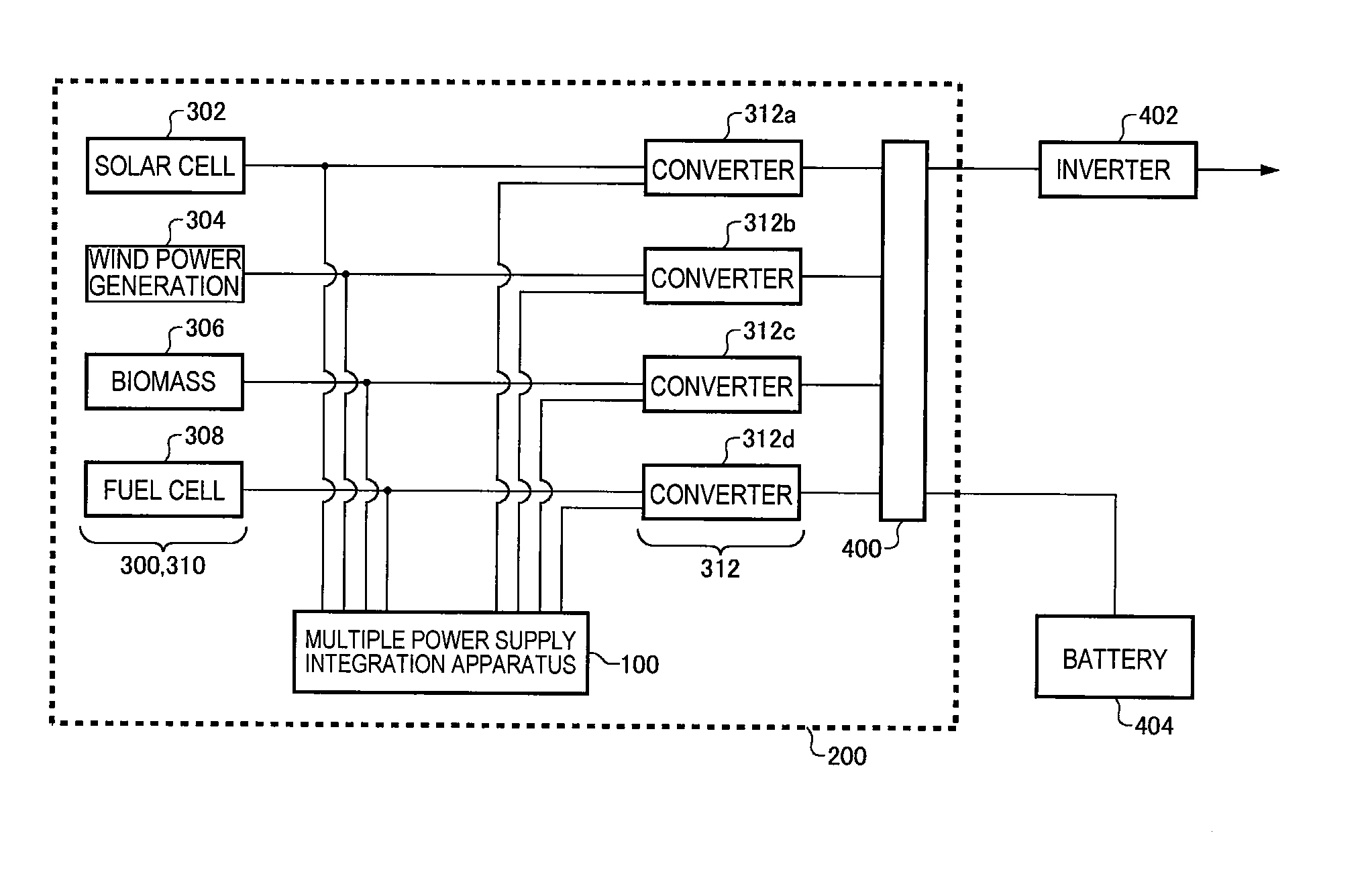
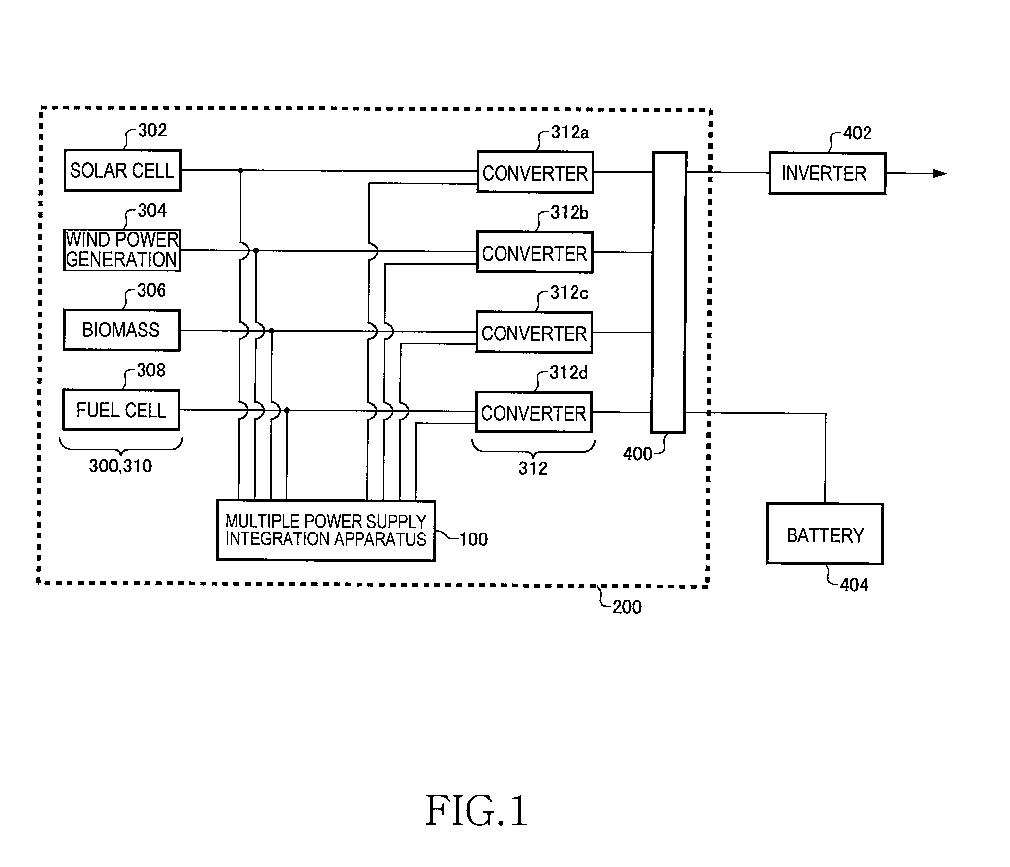
[0032]FIG. 1 is a hardware configuration diagram of a multiple power supply integration system 200 according to an embodiment of the present invention. The multiple power supply integration system 200 realizes stable power supply from the entire system by controlling a plurality of power supplies. In FIG. 1, “plurality of power supplies” corresponds to a solar cell 302, a wind power generation 304, a biomass 306, and a fuel cell 308 (each of which is simply referred to as “the power supply 300” unless specified otherwise). A power supply group 310 collectively indicates the plural power supplies 300.

[0033]The power supplies 300 generate electric power individually without interfering with one another. The power generated by each power supply 300 is referred to as “the source power”. The wind power generation 304, the biomass 306, and the fuel cell 308 ar...


PUM


Abstract

A multiple power supply integration apparatus measures electric power and stability of power supplies, outputs thereof having irregularity. Based on measured values of the electric power and the stability, certainty of entire supply of the electric power when a use allocation rate of the power supplies is changed is indexed as an evaluation value. The multiple power supply integration apparatus adjusts each converter according to a use allocation rate corresponding to a largest evaluation value, thereby adjusting a magnitude of the electric power supplied from each power supply to a common power line.

Description

BACKGROUND OF THE INVENTION[0001]1. Field of the Invention[0002]The present invention relates to a technique for controlling a power supply, and more particularly for controlling a plurality of power supplies.[0003]2. Description of Related Art[0004]The increase in energy demand is believed to continue in the future to follow development of the global economy, particularly economic growth of the Asian regions. For example, the International Energy Agency predicts that global demand of primary energy in the year 2030 increases by 66% from that in the year 2000. Under these social circumstances, expectation for renewable energy such as solar energy, wind power energy, biomass energy, geothermal energy, and tidal energy is growing.[0005]Despite its excellent properties of being clean and permanently usable, the renewable energy is pointed out to have a problem of unstable output. For example, with wind power generation, it is difficult to stably supply electric power because of a chang...

Claims


Application Information

Patent Timeline
IPC IPC(8): H02J1/00
CPCH02J1/102H02J2001/004H02J3/383H02J3/382Y02E10/563Y02E10/763H02J3/386H02J2300/30H02J2300/40H02J2300/28H02J2300/22H02J2300/20H02J2300/24H02J3/381Y02E10/56Y02E10/76H02J3/46
Inventor TAMAKI, KAZUTAKATAKAYAMA, ICHIRO
Owner TDK CORPARATION
Learn More