
Process for making an embossed web

Active Publication Date: 2010-09-16
THE PROCTER & GAMBLE COMPANY
View PDF15 Cites 32 Cited by
  • Summary
  • Abstract
  • Description
  • Claims
  • Application Information

AI Technical Summary

Problems solved by technology

While a vacuum forming process can be suitable for making a soft and silky polymeric web, a vacuum forming process is typically limited with respect to the amount of pressure capable of being exerted onto a precursor web.
A vacuum forming process is therefore an inefficient process in terms of how fast the process can be performed due to the heating step and the limited pressures generated by the process.
A hydroforming process, although capable of producing soft and silky polymeric webs, is typically a costly and inefficient process involving the use of high pressure and high temperature water jets and subsequent drying steps, including dewatering steps.
However, such embossing processes typically require extruding a molten resin onto a forming structure or heating a precursor web before placement onto a forming structure and then embossing to produce an embossed web.
However, these heating and cooling steps add undesirable cost and inefficiency, as well as complexity, to the process.
In addition, such embossing processes typically involve relatively large dwell times, which can result in slow, inefficient processes.
It is also typically difficult to impart relatively small scale texture to precursor webs using conventional embossing processes.

Method used


Image

  • Process for making an embossed web
  • Process for making an embossed web
  • Process for making an embossed web

Examples


example 1

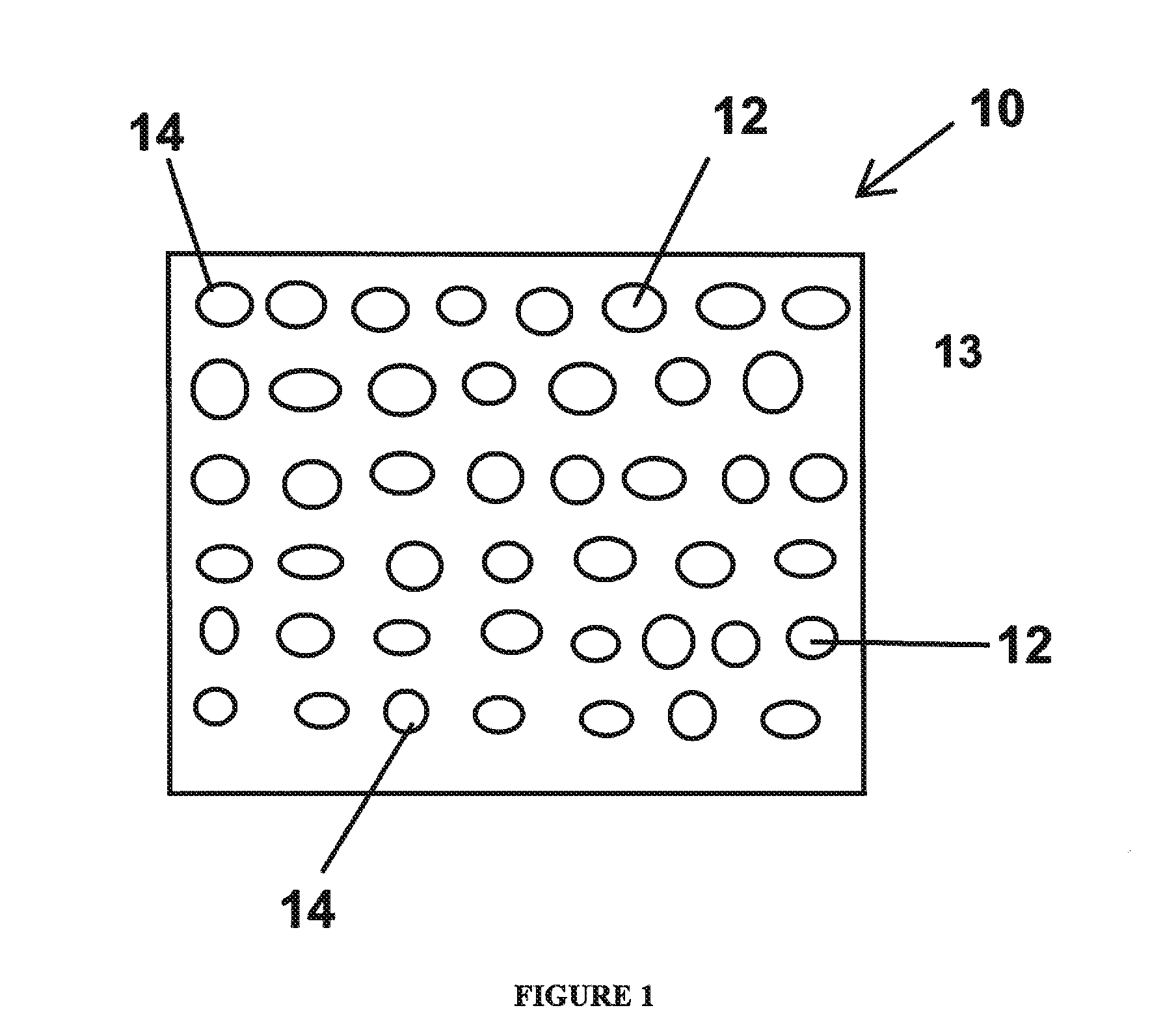
[0101]Embossed webs are produced using a static gas pressure plenum and a forming structure 10 having about 1550 apertures per square centimeter (about 10,000 apertures per square inch, 100 mesh metallic apertured plate). The forming structure is made of metal and has a thickness of about 1 mm. The apertures have a circular cross-section with a diameter of about 180 microns and a center-to-center spacing of about 250 microns. The sidewalls of the apertures are straight. As illustrated in FIG. 7, the apertures are offset relative to adjacent apertures.

[0102]The precursor web 34 utilized is a polyethylene film obtained from RKW US, Inc. that is about 15 microns thick and has a basis weight of 14.2 grams per square meter (“gsm”).

[0103]The embossing process is performed using a high speed research press with the forming structure preheated to a temperature of about 110° C. The high speed research press is described in detail in U.S. Patent Publication No. 2009 / 0120308, and is designed t...

example 2

[0104]Embossed webs are produced using a static gas pressure plenum and a forming structure 10 having about 1550 apertures per square centimeter (about 10,000 apertures per square inch, 100 mesh metallic apertured plate). The forming structure is made of metal and has a thickness of about 1 mm. The apertures have a circular cross-section with a diameter of about 180 microns and a center-to-center spacing of about 250 microns. The sidewalls of the apertures are straight. As illustrated in FIG. 7, the apertures are offset relative to adjacent apertures.

[0105]The precursor web 34 utilized is a polyethylene film obtained from RKW US, Inc. that is about 15 microns thick and has a basis weight of 14.2 grams per square meter (“gsm”).

[0106]The embossing process is performed using a high speed research press, as described in Example 1. The press is operated to simulate a forming structure roll diameter of 205 mm. The forming structure is preheated to a temperature of about 90° C. The precurs...


PUM

PropertyMeasurementUnit
Temperatureaaaaaaaaaa
Lengthaaaaaaaaaa

Abstract

A process for making an embossed web. A precursor web is provided between a forming structure and a static pressure plenum. The forming structure has a plurality of discrete apertures or depressions. Pressure is provided by the static pressure plenum against the precursor web and the forming structure to force the precursor web into the apertures or depressions of forming structure to form the embossed web. The resulting embossed web has a plurality of discrete extended elements.

Description

CROSS REFERENCE TO RELATED APPLICATION[0001]This application claims the benefit of U.S. Provisional Application No. 61 / 159,906, filed Mar. 13, 2009.FIELD OF THE INVENTION[0002]The invention relates to a process for making an embossed web comprising a plurality of discrete extended elements.BACKGROUND OF THE INVENTION[0003]Web materials, such as thermoplastic films, have a variety of uses including component materials of absorbent articles (such as topsheets and backsheets), packaging (such as flow wrap, shrink wrap, and polybags), trash bags, food wrap, dental floss, wipes, electronic components, and the like. For many of these uses of web materials, it can be beneficial for the web material to have a textured surface which can provide the surface of the web material with a desirable feel, visual impression, and / or audible impression.[0004]Polymeric webs exhibiting a soft and silky tactile impression can be made via a vacuum forming process or a hydroforming process. With a typical ...

Claims


Application Information

Patent Timeline
IPC IPC(8): B29C43/56
CPCB26F1/26B29C66/934B29C59/04B29C59/06B29C65/56B29C66/21B29C66/45B29C66/8266B29C66/82661B29C66/91935B29C66/939B29C66/949B31F2201/0733B31F2201/0738B44C1/24B29D7/01B29C66/81423B29C66/9121B29C66/91216B29C66/91411B29C66/9161B29C66/919B29C66/81433B29C59/022B29C66/71B29C66/1122B30B3/005B29K2077/00B29K2067/003B29K2067/00B29K2033/12B29K2029/04B29K2027/18B29K2023/12B29K2023/0633B29K2023/0625B29K2023/06B29K2005/00B29K2067/043B29K2067/046
Inventor GRAY, BRIAN FRANCISGROSS, SARAH BETHVAN VALKENBURG, CURTIS HUNTERCOE, RICHARD GEORGESTONE, KEITH JOSEPH
Owner THE PROCTER & GAMBLE COMPANY
Learn More