
Method of manufacture of one-piece composite parts using a two-piece form including a shaped polymer that does not draw with a rigid insert designed to draw

a composite part and one-piece technology, applied in the field of one-piece composite parts manufacturing, can solve the problems of high cost, large complexity and expense, and complex process known processes for fabricating castable composite parts, and achieve the effect of reducing the cost of manufacturing related molds, reducing the complexity and expense of manufacturing, and reducing the complexity of manufacturing

Active Publication Date: 2010-09-16
RAYTHEON CO
View PDF5 Cites 15 Cited by
  • Summary
  • Abstract
  • Description
  • Claims
  • Application Information

AI Technical Summary

Benefits of technology

[0013]The present invention provides a low-cost method of manufacture of one-piece composite parts having shapes that do not draw and, in particular, wings and wing shells with twist or taper and camber.
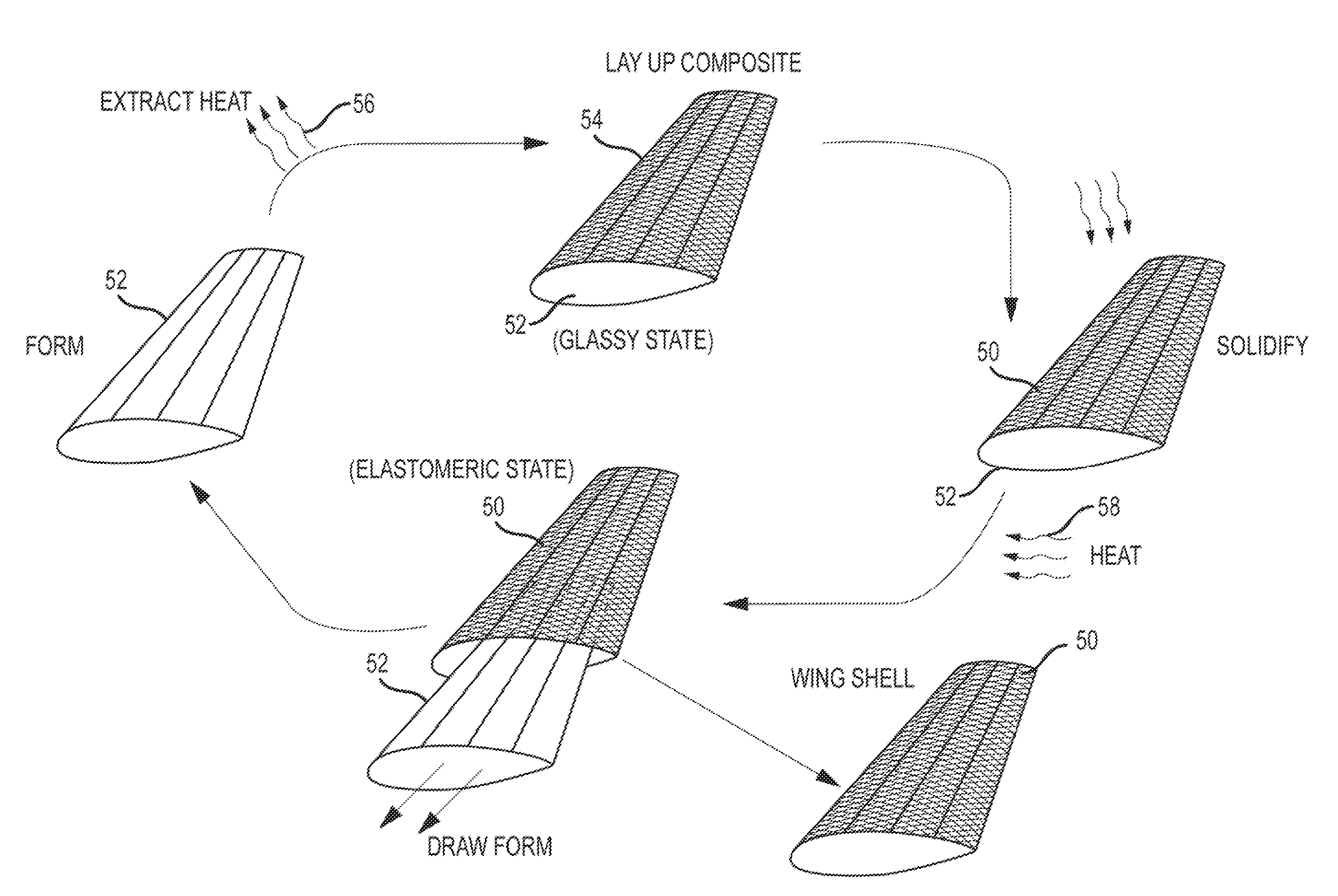
[0014]This is accomplished with a shaped polymer form. A polymer is fabricated into the shape of a form for a one-piece composite part and then solidified by curing, setting, hardening or otherwise solidifying the polymer. The shaped polymer form has a shape that does not draw from the one-piece composite part. Composite material is laid up on the form and solidified to form the composite part. The stiffness desired to lay up the composite material can be provided by operating in the polymer form's glassy state, forming the shaped polymer form with a hollow core and placing a rigid insert designed to draw inside the hollow core or through a combination of both, in its elastomeric state the form becomes pliable (without relaxing to a different memorized shape) and can be drawn out of the one-piece composite pan. Because the shape of the form does not draw, the form deforms as it is drawn. If used, the rigid insert is drawn out prior to removing the shaped polymer form. Upon removal, the polymer in its elastomeric state returns to its original shape for the composite part. The form may be used once and thrown away or reused to form multiple composite parts of the same shape. The polymer may be formed into the form using inexpensive processes such as compression or injection molding. This approach does not require a SMP in that it does not utilize a memorized shape and does not require the polymer to be inflated and reinflated into the desired form shape at each use.

Problems solved by technology

Known processes for fabricating castable composite parts are very complicated, and expensive.
A large portion of the complexity and expense is associated with manufacturing related molds.
When these parts are manufactured using a form or mandrel, there is typically a problem with removing the form (mandrel) from the finished part.
These types or air vehicles may place high loads on the wings and require the capabilty to maneuver rapidly.
In both processes, an expensive machining procedure is required to form each wing that wastes considerable materials.
A wing with wist or taper and camber cannot be laid up on a reusable form because the form will not draw out and so cannot be removed.
However, this approach does not provide a one-piece wing shell, hence wing, requires additional assembly and potentially reduces the structural integrity of the wing.

Method used


Image

  • Method of manufacture of one-piece composite parts using a two-piece form including a shaped polymer that does not draw with a rigid insert designed to draw
  • Method of manufacture of one-piece composite parts using a two-piece form including a shaped polymer that does not draw with a rigid insert designed to draw
  • Method of manufacture of one-piece composite parts using a two-piece form including a shaped polymer that does not draw with a rigid insert designed to draw

Examples


Embodiment Construction

[0026]The present invention provides a low-cost method of manufacture of one-piece composite parts having shapes that do not draw and, in particular, wings and wing shells with twist, or taper and camber. A polymer form is created for a one-piece composite part. This form may be manufactured using very inexpensive manufacturing processes such as compression or injection molding. The form does not have to be shaped during the manufacture of the composite parts or re-shaped to reuse the form. This may dramatically reduce the capital investment required to manufacture composite parts.

[0027]The process of manufacture using the polymer form described herein may be applied to any one-piece composite part in which the shape of the form does not draw from the one-piece composite part formed thereon. The terms “designed to draw” and “does not draw” are well known in the industry, “Designed to draw” means that the form may be pulled (or drawn) from the composite part without breaking or defor...


PUM

PropertyMeasurementUnit
shapeaaaaaaaaaa
Young's modulusaaaaaaaaaa
elastomericaaaaaaaaaa

Abstract

A polymer is formed into the shape of a one-piece composite part and then solidified by curing, setting, hardening or otherwise solidifying the polymer to form a shaped polymer form having a shape that does not draw. Composite material is laid up on the form and solidified to from the composite part. The rigidity required of the form to lay up the composite part can he provided by operating in the polymer form's glassy state, forming the shaped polymer form with a hollow core and placing a rigid insert designed to draw inside the hollow core with the polymer form in its elastomeric state or through a combination of both. In its elastomeric state the form becomes pliable (without relaxing to a different memorized shape) and can he drawn out of the one-piece composite part. Because the shape of the form does not draw, the form deforms as it is drawn. If used, the rigid insert is drawn out prior to removing the shaped polymer form. Upon removal, the polymer form in its elastomeric state returns to its original shape. The form may be used once and thrown away or reused to form multiple composite parts of the same shape.

Description

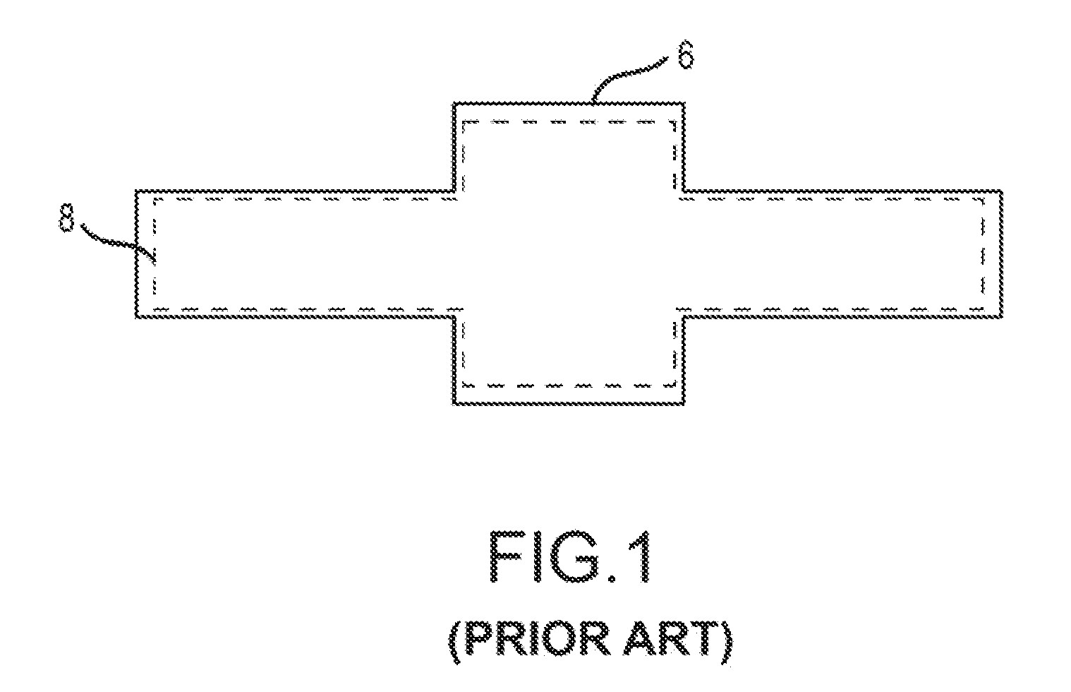
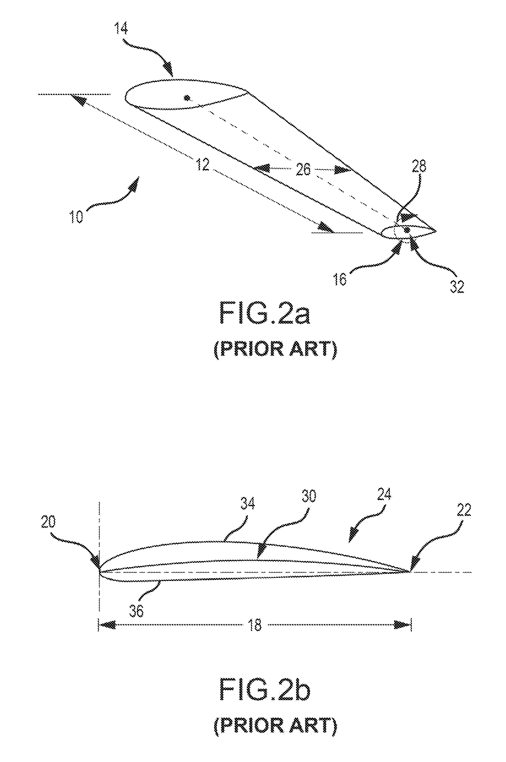
BACKGROUND OF THE INVENTION[0001]1. Field of the Invention[0002]This invention relates to the manufacture of one-piece composite pails including wings and wing shells.[0003]2. Description of the Related Art[0004]Known processes for fabricating castable composite parts are very complicated, and expensive. A large portion of the complexity and expense is associated with manufacturing related molds. Nearly any part can be constructed as a composite part by various production methods such as filament winding, tape placement, overbraid, chop fiber roving, coating, painting, dripping, hand lay up, resin soaked, or other composite processing technique and curing process.[0005]When these parts are manufactured using a form or mandrel, there is typically a problem with removing the form (mandrel) from the finished part. For very simple parts, the form can be “designed to draw” e.g. the form can he removed from the one-piece composite part by simply drawing (pulling) the form out of the part....

Claims


Application Information

Patent Timeline
Patent Type & Authority Applications(United States)
IPC IPC(8): B29C45/14
CPCB29C33/505B29L2031/3085B29C70/30B33Y30/00
Inventor SANDERSON, TERRY M.
Owner RAYTHEON CO
Learn More