Chilling economizer

a technology of economizer and economizer body, which is applied in the direction of refrigerating machines, climate sustainability, sorption machines, etc., can solve the problems of feedwater heating deficit, part of exhaust bypassing economizer, etc., and achieves the effect of reducing aarc heat, avoiding economizer corrosion, and increasing chilling

Inactive Publication Date: 2010-09-16
ERICKSON DONALD CHARLES
View PDF30 Cites 11 Cited by
  • Summary
  • Abstract
  • Description
  • Claims
  • Application Information

AI Technical Summary

Benefits of technology

[0012]The above and other useful objects are accomplished by providing a thermally activated chilling unit that is powered by a heat recovery unit (HRU) located in the boiler exhaust. The HRU can be directly supplied with working fluid from the thermally activated chiller, that is desorbed therein, normally referred to as a heat recovery vapor generator (HRVG). Preferably the HRVG is colocated with the economizer in the boiler exhaust. Alternatively, the HRU can be supplied a working fluid that in turn supplies heat to the thermally activated chiller. The preferred embodiment of thermally activated chiller is an ammonia-water absorption refrigeration cycle (AARC). An essential aspect of the invention is that the AARC reject heat is used to preheat the boiler feedwater and makeup feedwater, for example before it is sent to the economizer. That supplies three important benefits: it allows more of the exhaust heat to be sent to the AARC, thus increasing the amount of chilling; it reduces the amount of AARC heat that must be rejected to ambient, through a cooling tower or the like; and it raises the feedwater temperature above the exhaust dewpoint, so economizer corrosion is avoided.
[0013]Further to this disclosure, it is desirable to route the AARC working fluid in direct countercurrent contact with the exhaust. This allows it to extract more useful heat from the exhaust, i.e. down to a lower temperature, and also increases the temperature of the AARC reject heat, thus allowing more reject heat to be transferred to the feedwater.

Problems solved by technology

However the drawback of the parallel configuration is that when there are times the AARC is not being used, e.g. at mild ambient conditions, and is turned off, part of the exhaust bypasses the economizer.
Since the feedwater no longer receives preheat from the idle AARC, there will be a deficit in feedwater heating.

Method used


Image

  • Chilling economizer
  • Chilling economizer
  • Chilling economizer

Examples


Embodiment Construction

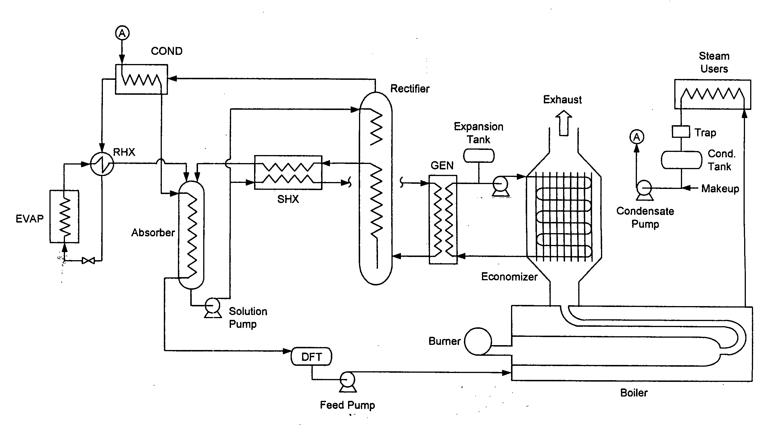
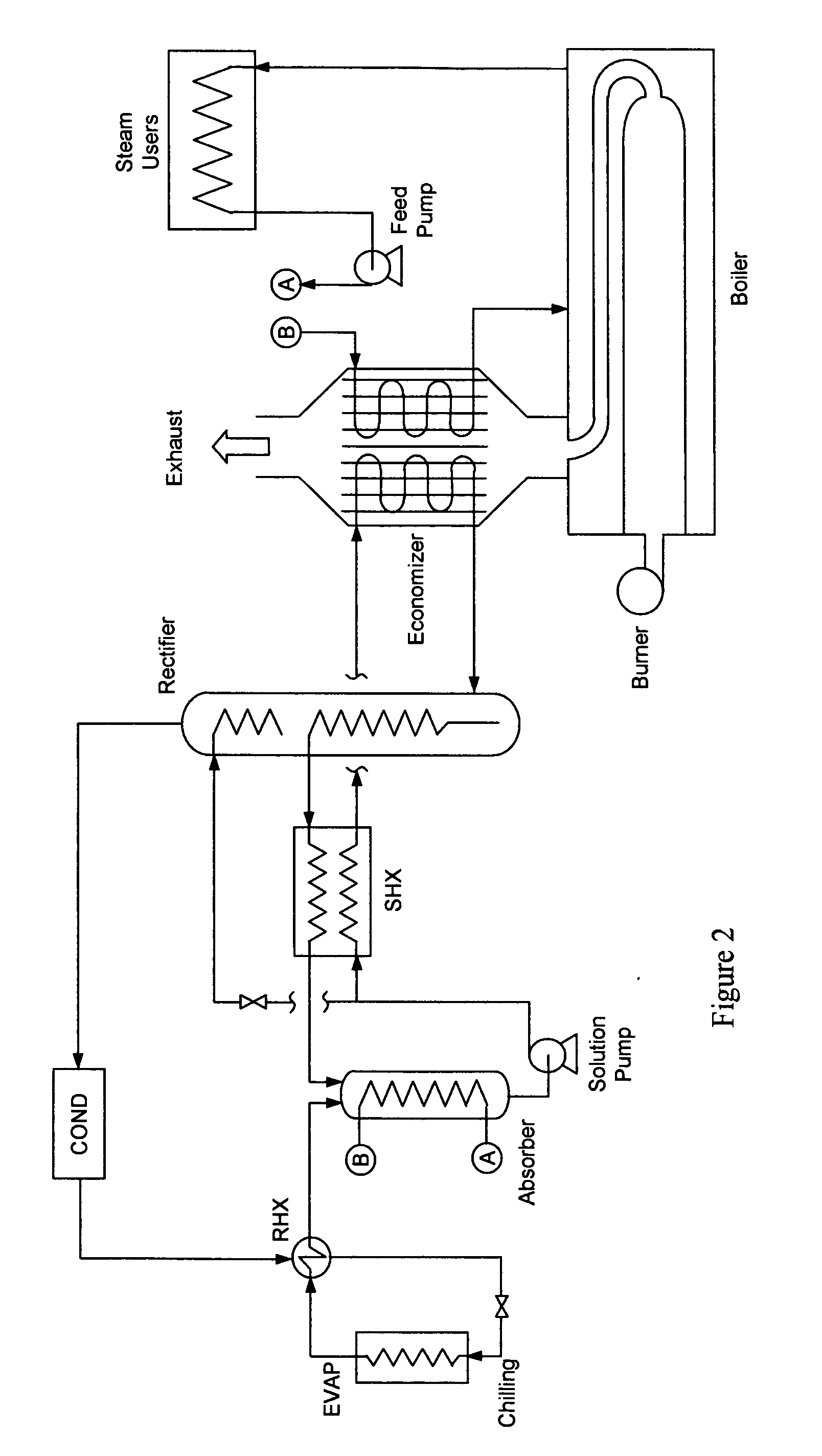
[0026]It would be possible to mount the HRVG downstream of the economizer, i.e. at its cold end, and just use the final waste heat of the exhaust to make chilling. However that would waste about half of the actual potential of that exhaust to produce chilling. The features desirable to achieve high levels of chilling are: to colocate the HRVG of the AARC with the economizer, such that higher driving temperatures are available to the HRVG; to achieve maximum useful temperature glide in the HRVG by supplying it directly with pumped and preheated solution; to rectify the desorbed solution to higher ammonia purity so as to get more useful chilling from a given amount of desorbed fluid; and to preheat feedwater with absorber reject heat. The latter step has two benefits: more of the exhaust heat becomes available to the HRVG; and the economizer feed is warm enough (e.g. above 140° F.) that acid condensation of the exhaust gas is not a concern. Note that this requires that absorber heat b...


PUM


Abstract

Chilling is produced from heat that is normally wasted in the economizer section of a steam boiler. A thermally-activated ammonia-water absorption chiller is powered by a heat recovery unit. The heat recovery unit supplies boiler exhaust heat to desorb the working fluid of the chiller. That can be directly, such that the heat recovery unit is a heat recovery vapor generator that can be colocated with an economizer, in parallel or series. The exhaust heat can alternatively be supplied to the AARC indirectly, via a heat transfer loop and a separate generator. The desorbed ammonia vapor is rectified, condensed, and then used to produce the chilling. The heat released in the chiller when low pressure ammonia vapor is re-absorbed is used to preheat the boiler feedwater.

Description

BACKGROUND[0001]With steam boilers, it is good practice to include an economizer or feedwater heater to capture more useful energy from the exhaust. This increases boiler efficiency and reduces stack temperature. Thus it is surprising to learn that there is actually a lot of wasted availability that still remains even when economizing. The stack temperature is still well above ambient, and the economizing step employs very large temperature differentials, thus generating the entropy. The overall purpose of this disclosure is to make beneficial use of this presently wasted availability.[0002]Many steam boilers are found in applications where refrigeration is also required (or would be useful). Examples include food processors, hospitals, laundries, hotels, and process industries. Additional examples are combined cycle plants and cogeneration plants where the boilers are heated by exhaust from the prime movers. On warm days those prime movers benefit markedly from chilling the inlet a...

Claims


Application Information

Patent Timeline
IPC IPC(8): F25B15/00
CPCF25B15/02Y02B30/62F25B15/04Y02A30/27
Inventor ERICKSON, DONALD CHARLES
Owner ERICKSON DONALD CHARLES
Why Eureka
Try Eureka