
Mist Dispersal System for Air Conditioners

a technology of air conditioner and dispersal system, which is applied in air humidification systems, heating types, lighting and heating apparatus, etc., can solve the problems of increased pollution, increased energy consumption, and shorten the life of cooling systems, so as to prevent unwanted scale deposits or corrosion, reduce the electrical energy of device operation, and inhibit the corrosion of condenser parts.

Inactive Publication Date: 2010-09-16
NICODEM HARRY E
View PDF29 Cites 11 Cited by
  • Summary
  • Abstract
  • Description
  • Claims
  • Application Information

AI Technical Summary

Benefits of technology

[0015]As described in the examples herein, direct actuation of the valve by the condenser fan airflow may be accomplished by a number of methods. The dynamic pressure differential of the condenser fan airflow may be ported directly to an air piloted valve to actuate flow to the misting nozzles. Alternatively, an aerodynamic structure such as an air-foil may be mechanically coupled to directly actuate the valve. Such an aerodynamic shape will improve on prior art by minimizing the blockage of the condenser fan airflow.
[0017]In the case of a bi-stable or latching solenoid valve, the valve only requires electrical energy to change states between the open and closed position, but requires no electrical energy to remain in either the open or closed position. A bi-stable or latching valve has the advantage of using the minimum amount of electrical energy for device operation. A bi-stable or latching valve requires a fail-safe provision in the electrical supply circuit to ensure that the valve closes in situations where a loss of power has occurred. This fail-safe feature may be accomplished by a capacitor that is charged before the valve opens and then discharges energy to close the valve if a loss of power occurs.
[0018]The distribution lines lead to sprayer features that disperse mist over the condenser's heat transfer coils. In the preferred embodiment, the distribution line(s) and fluid supply lines contain in-line combination particulate and poly-phosphate filter to prevent valve clogging, scale deposits, and inhibit corrosion of condenser parts, thus maintaining the full potential for fluid flow therein. The filter housing is provided with a feature that prevents fluid flow when the charge of polyphosphate crystals has been consumed. This ensures that the polyphosphate filter is replaced preventing unwanted scale deposits or corrosion when filter device use continues after depletion of the polyphosphate crystals.
[0019]In another embodiment, the sprayer features include misting nozzles mounted within decorative structures, possibly at several locations on the distribution and fluid supply lines. The sprayers may have integral features (decorative or not) that assist in the dispersion of mist by rotating under the force of the water supply pressure. Such a rotating feature would cause the sprayer nozzle(s) to rotate through a circular path increasing the area of mist application and thus the overall effectiveness of the misting process.

Problems solved by technology

These air cooling systems are generally inefficient because of the significant amount of energy necessary to cool a large amount of air, which results in a shorter life span of the cooling systems, greater energy consumption, increased levels of pollution, and high operating costs.
The decrease in demand on the compressor unit will lead to a longer life as well as saving money, energy, and unnecessary pollution.
The currently available methods of applying mist to a condenser are lacking in certain areas; with each containing certain inefficiencies and disadvantageous aspects.
These two mist application methods are limited by the fact that the paddle actuators block part of the condenser's airflow, which reduces the potential energy saving as a result of applying the mist.
Thus, an inefficient two sprayer systems would be running at the same time.
The prior art inventions require a high level of energy, have insufficient mist sprayer positions, an inadequate method of keeping the pipes unblocked, and / or have other disadvantages.

Method used


Image

  • Mist Dispersal System for Air Conditioners
  • Mist Dispersal System for Air Conditioners
  • Mist Dispersal System for Air Conditioners

Examples


Embodiment Construction

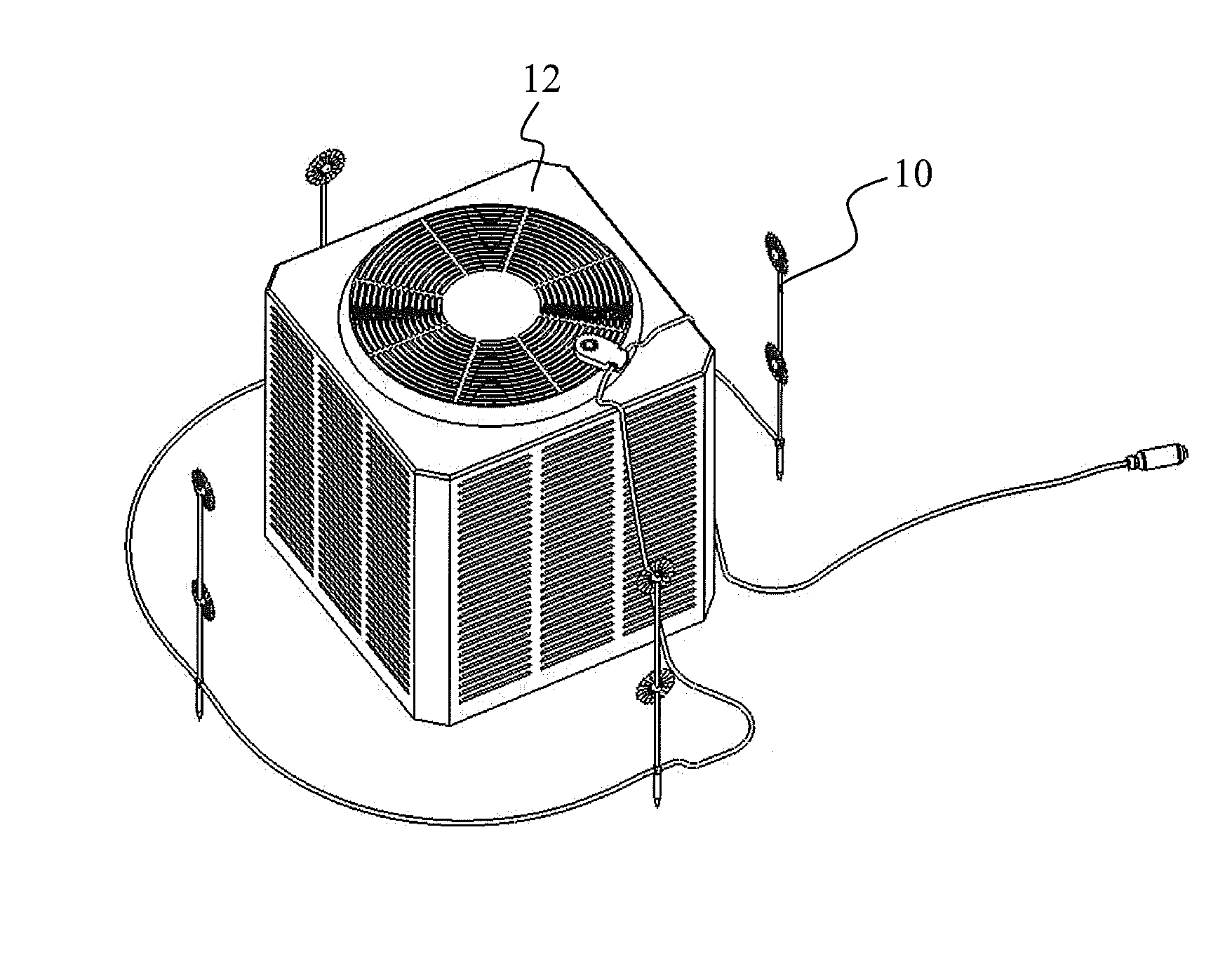
[0034]FIG. 1 shows an embodiment of the present invention improving on prior art systems that apply water or mist to a condenser by utilizing a mist dispersal system 10 for dispersing a water or vapor mist over a condenser unit 12. As described herein, dispersing water or vapor mist onto the condenser of an air cooling unit, improves the efficiency of the air cooling function in air conditioners. The present invention provides a novel apparatus and method for increasing the efficiency of the air conditioner.

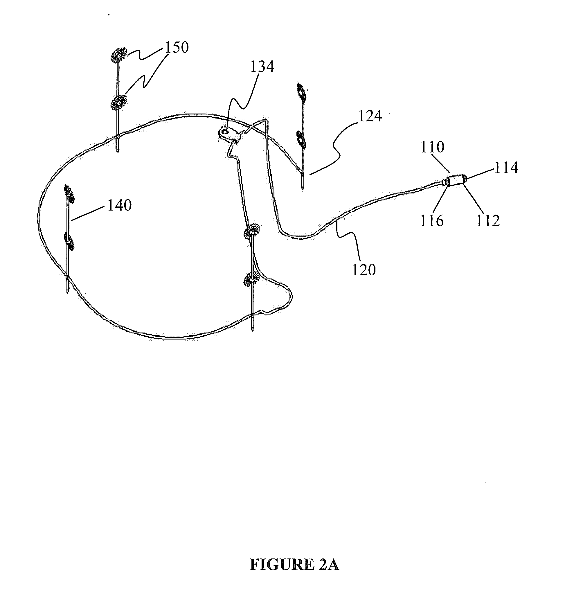
[0035]FIG. 2A shows the mist dispersal system 10 of the present invention which includes a number of components, including the system's main filter 110. In the preferred embodiment the filter 110 is an in-line particulate filter such as a polyphosphate crystal filter 110, although other types of filters may be used. The system's filter 110, which can also serve as a coupling attachment, is shown as containing a garden hose fitting 112. This is the point of connection to a fluid s...


PUM


Abstract

An apparatus for increasing the efficiency of air conditioning units, and methods of improving the efficiency of the air cooling function in air conditioners is disclosed by dispersing a water or vapor mist onto the heat transfer coils of a condenser used in an air cooling unit to effectively and efficiently reduce the use of power by the condenser and reduce the time the condenser must run. The apparatus includes fluid lines and a filter, the function of which is to remove particulate matter from the fluid, prevent scale formation, and provide a coating on the surface of certain parts of the condenser. The filter is configured to stop the flow of fluid when the filter can no longer provide these functions.

Description

PRIORITY STATEMENT[0001]This application claims the benefit of U.S. Provisional Application No. 61 / 209,946, filed Mar. 12, 2009.FIELD OF THE INVENTION[0002]This invention relates to highly efficient air conditioning units; and more specifically, to a method of improving the efficiency of the air cooling function in air conditioners by dispersing a water or vapor mist onto the condensers of air cooling units effectively and efficiently thereby reducing the use of power by the condenser and reducing the time the condenser must run.[0003]The present invention further comprises an in-line filter for removing particulate matter from the fluid, sequestering dissolved solids in the hard water to prevent the formation of scale on the condenser and providing a coating on the surface of the condenser to prevent corrosion. The filter is configured to stop the transfer of fluid when the filter has run its useful life and is no longer providing all of these functions.BACKGROUND OF THE INVENTION[...

Claims


Application Information

Patent Timeline
IPC IPC(8): F28D5/00
CPCF24F2006/146F28D5/00F25B2339/041F25B39/04
Inventor NICODEM, HARRY E.
Owner NICODEM HARRY E
Learn More