
Panel and relative manufacturing system and method

a technology of manufacturing system and relative, applied in the direction of paper/cardboard containers, lamination, containers, etc., can solve the problems of difficult to achieve, need for a new type of hardware, and inability to provide effective adhesion of edging materials

Inactive Publication Date: 2010-09-09
NALDI VALTER
View PDF9 Cites 10 Cited by
  • Summary
  • Abstract
  • Description
  • Claims
  • Application Information

AI Technical Summary

Benefits of technology

[0019]It is an object of the present invention to provide a panel and relative manufacturing method and system, designed to eliminate the aforementioned drawbacks.

Problems solved by technology

On the other hand, using current techniques, they fail to provide for effective adhesion of the edging material, for lack of a compact layer, between the outer layers, to which to attach the joins of the edging material at the corners.
Another drawback of this new type of panel is the need for a new type of hardware fittings to ensure furniture of strong make, and which appears to be difficult to achieve on account of the extremely weak nature of the inner layer of the sandwich panel.
That is, since grooving tools are necessarily circular, and not being possible to run out from the ends of the first two sides already edged, tool entry and exit along the second two sides must be programmed accordingly, thus resulting in incomplete grooves along these sides; and the inside end portions of the reinforcing strips must also be rounded off to insert them inside the ends of the incomplete grooves in the second two sides.
This results in excessive use of wood, on account of the strip also being fitted to parts of the edge where it is not needed, and the difference between the standard length of the wood strips and the actual length of the panel results in considerable waste.

Method used


Image

  • Panel and relative manufacturing system and method
  • Panel and relative manufacturing system and method
  • Panel and relative manufacturing system and method

Examples


Embodiment Construction

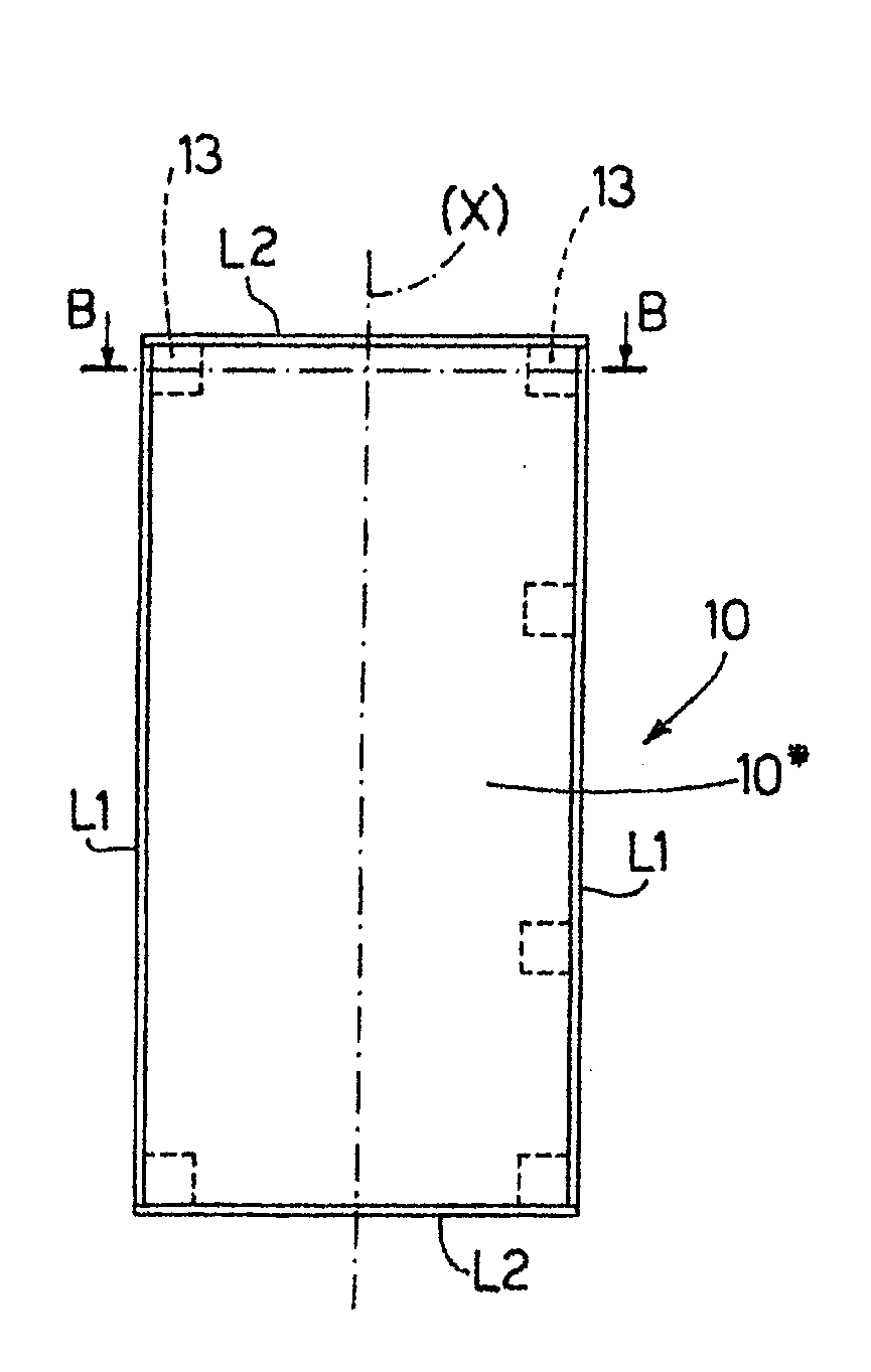
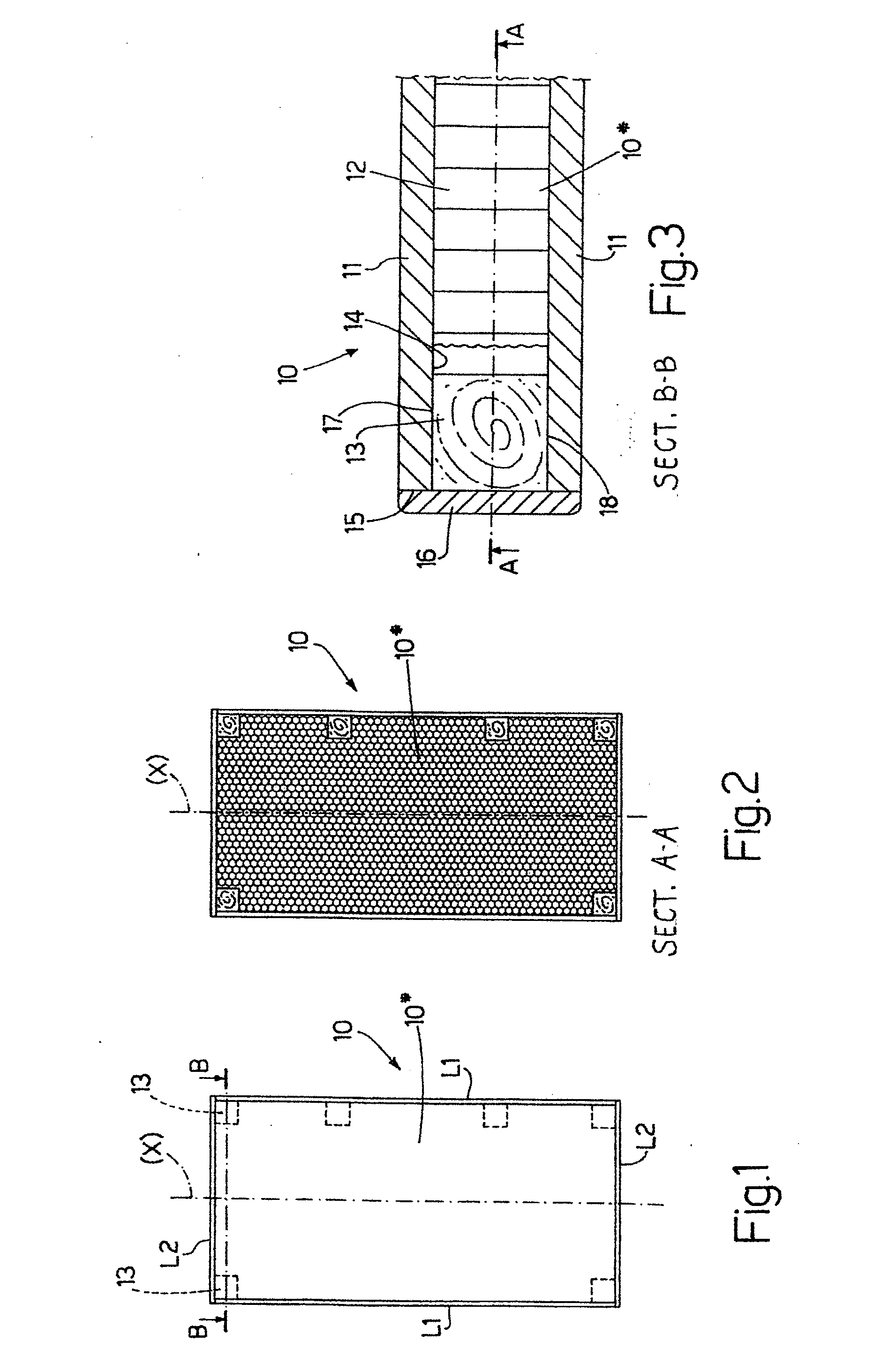
[0034]Number 10 in FIGS. 1, 2, 3 indicates as a whole a panel in accordance with the present invention.

[0035]Panel 10 comprises a sandwich blank 10* cut from a strip (not shown) (or from a large panel) produced in a manufacturing system (not shown). In the FIGS. 1, 2, 3 embodiment, sandwich blank 10* is rectangular, has a longitudinal axis of symmetry (X), and comprises two longitudinal sides L1 parallel to axis (X), and two parallel transverse sides L2 crosswise to axis (X).

[0036]As will be seen below, the finished panel 10 is edged along all or part of its perimeter (see below).

[0037]Blank 10* has a sandwich structure comprising two solid outer layers 11 (FIG. 3) which may be made, for example, of chipboard or MDF, and between which is interposed a supple inner layer 12 advantageously made of “honeycombcardboard or foam material.

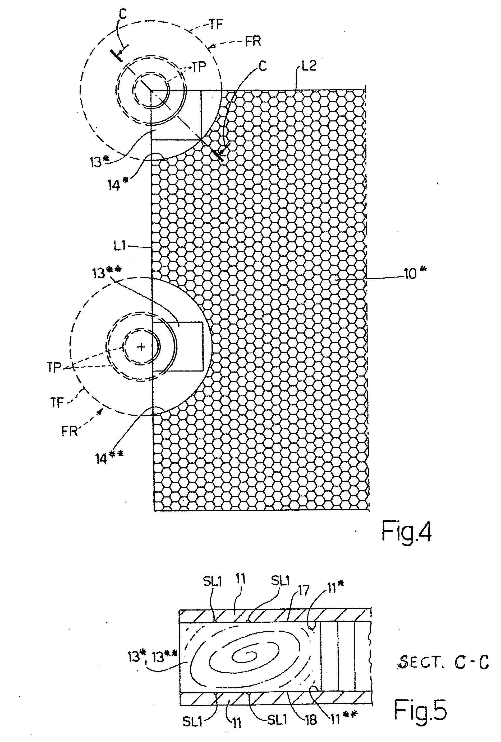
[0038]Panel 10 in FIGS. 1, 2, 3 is characterized by comprising spacing block-shaped plugs 13 inserted, between the two outer layers 11, inside cavities ...


PUM


Abstract

A fully or partly edged panel (10; 200) of wood or wood fibre. The panel (10; 200) includes a sandwich blank (10*; 200*) having outer layers (11) of solid consistency, and at least one supple inner layer (12) with a lightweight, possibly “honeycomb” or supple foam material, structure. The panel (10; 200) is characterized by having at least one spacing block-shaped plug (13; 213) inserted between the two outer layers (11) of the sandwich blank (10*; 200*), and by the peripheral outer faces (15) of the sandwich blank (10*; 200*) being edged with an adhesive edging strip (16). Also described are methods and systems (100; 1000) for manufacturing the panel (10; 200).

Description

TECHNICAL FIELD[0001]The present invention relates to a panel and relative manufacturing system and method.[0002]As is known, panels currently used to make furniture are made of wood-fibre materials (chipboard, MDF, etc.) which, by their very nature, have numerous advantages as regards the finishing of furniture component parts.[0003]In particular, being fairly compact, they are ideal for edging, by having a whole surface on which to glue the edging material, and for fitting the necessary manufacturing and assembly hardware (hinges, dowels, etc.).[0004]In recent times, however, conventional panels of the above type have begun to pose serious problems. In particular, they are not light, and, when used in cabinet-making, result in extremely heavy furniture. Moreover, given the increasing shortage of wood, the cost and shortage of 100% wood-fibre panels mean they are used less and less.[0005]A new type of panel is therefore required to replace conventional types.[0006]Two essential fea...

Claims


Application Information

Patent Timeline
IPC IPC(8): B32B3/02B32B3/10B32B3/30B29C65/78B32B38/10
CPCB32B3/22E04C2/296E04C2/365B32B21/042Y10T156/1062B32B2479/00Y10T428/24612Y10T428/13Y10T428/24752B32B2307/50Y10T156/10Y10T156/1052Y10T156/1082Y10T29/49629Y10T29/49787
Inventor NALDI, VALTER
Owner NALDI VALTER
Learn More