Circuit and Method for Matching Current Channels

a current channel and circuit technology, applied in pulse manipulation, pulse technique, instruments, etc., can solve the problems of inability to easily match channels with one, inability to achieve uniform brightness across the panel, and inability to achieve practical approaches, etc., to achieve the effect of not increasing the scale and complexity of the circuit significantly

Inactive Publication Date: 2010-09-09
RICHTEK TECH
View PDF11 Cites 1 Cited by
  • Summary
  • Abstract
  • Description
  • Claims
  • Application Information

AI Technical Summary

Benefits of technology

[0005]In view of the problems of the prior art, the present invention provides a circuit for matching a plurality of current channels in current amount without increasing the scale and complexity of the circuit significantly.

Problems solved by technology

Such increasing number of channels causes a problem that current channels can not be easily matched with one another in current amount, and accordingly the brightness across the panel is not uniform.
However, such an approach is not practical because it requires an enormous sophisticated circuit and a time-consuming check procedure.

Method used


Image

  • Circuit and Method for Matching Current Channels
  • Circuit and Method for Matching Current Channels
  • Circuit and Method for Matching Current Channels

Examples


Embodiment Construction

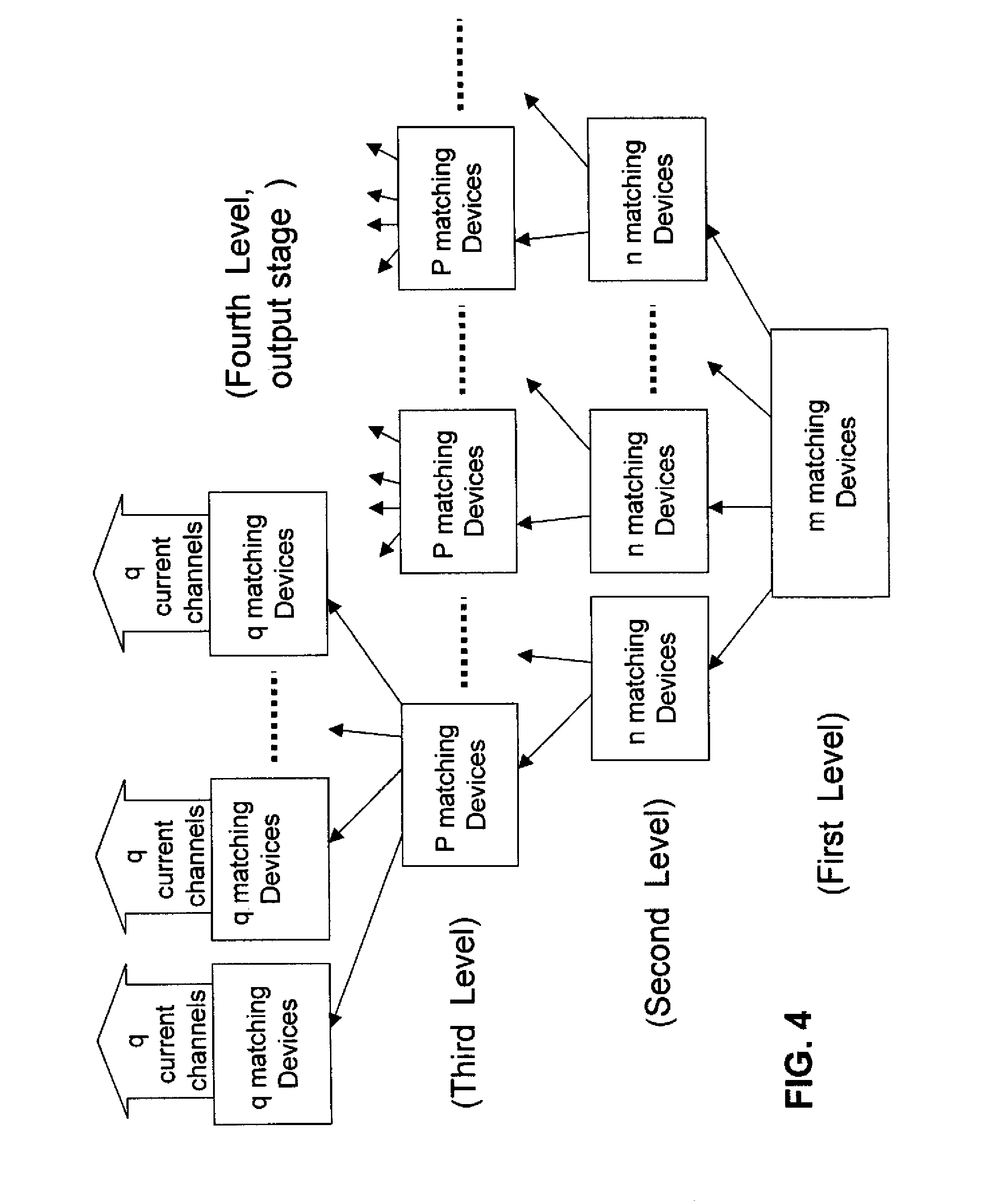
[0027]The present invention will first be explained with respect to its principle. As described in the section “Description of Related Art”, the number of channels of OLEDs in a large size OLED panel may be more than several hundred or even up to several thousand, and it is difficult to calibrate their matching conditions one by one. Therefore, according to the present invention, a “hierarchical tree structure” is employed to solve the above problem. Referring to FIG. 4, a 4-level hierarchical tree structure is used for current-matching in a circuit. As shown in the figure, m devices are allotted to the first level and are matched with one another, and m sets, each of which has n devices matched with one another, are allocated to the second level. At the third level, each device at the second level corresponds to p devices, and each of the p devices of the same set is matched with the other devices of the same set. Similarly, at the fourth level, each device at the third level corre...


PUM


Abstract

The present invention discloses a current-matching method comprising steps of: providing a plurality of current channels; grouping the plurality of current channels into W sets, each of which has Q channels; and matching the channels of the same set in current, where both W and Q are integers greater than or equal to 2.

Description

FIELD OF THE INVENTION[0001]The present invention relates to a circuit and a method for matching current channels, and in particular, to a circuit and a method capable of matching a plurality of current channels with one another in current amount. The circuit and the method are particularly suitable for Organic Light Emitting Diode (abbreviated as OLED hereinafter) panels.BACKGROUND OF THE INVENTION[0002]FIG. 1 illustrates an example of a conventional control circuit for a passive OLED panel. As shown in FIG. 1, a circuit 10 includes n OLEDs OLED1-OLEDn, which are placed in channels 11-1n, respectively, and the conduction of the channels 11-1n are controlled by corresponding row signals RS1-RSn. In the passive OLED panel, the raw signals RS1-RSn turn ON the channels in turn so as to form a perceivable image by vision persistence. The brightness of the OLEDs OLED1-OLEDn correspond to the current amounts flowing in the channels 11-1n, respectively. Each of the channels 11-1n is contro...

Claims


Application Information

Patent Timeline
Patent Type & Authority Applications(United States)
IPC IPC(8): H05B37/02
CPCH05B33/0896H05B33/0827H05B45/46H05B45/60Y02B20/30G05F3/08G09G3/30G09G3/32
Inventor LIU, JING-MENG
Owner RICHTEK TECH
Why Eureka
Try Eureka