Detection device, detecting method and detection program

a detection device and detection method technology, applied in measurement devices, using reradiation, instruments, etc., can solve the problems requiring hardware performance improvement, and information on the envelope becoming no longer normal, etc., to achieve the effect of increasing cost and circuit scal

Active Publication Date: 2015-07-14
FURUNO ELECTRIC CO LTD
View PDF17 Cites 3 Cited by
  • Summary
  • Abstract
  • Description
  • Claims
  • Application Information

AI Technical Summary

Benefits of technology

[0006]Therefore, this invention is made in view of the above situations, and provides a detection method, device and computer program, which prevents a saturation of a reception signal, without increasing cost and a circuit scale.
[0008]That is, when the reception signal reaches the saturation condition or becomes close to the saturation condition, the transmitting condition setting module performs setting to reduce the transmitting power, thereby preventing the saturation of the reception signal.
[0012]When an intensity lower than the saturation condition by a predetermined difference is detected, the transmitting power may be increased. For example, the reception signal reaches the saturation condition and the transmitting power is reduced, and, after that, when the water bottom depth changes or a bottom sediment changes so that the intensity of the water bottom echo becomes very low, the transmitting power is increased to improve the S / N ratio.
[0016]As described above, according to the aspects of the invention, the reception signal will not be saturated, without increasing cost and a circuit scale.

Problems solved by technology

However, when a reception signal is saturated, information on the envelope becomes no longer normal, and an appropriate pulse compression may be unable to be performed.
A drawback of this technique is that an improvement of hardware performance is needed to widen the receiving dynamic range.
Therefore, there creates a new problem that cost and a circuit scale increase.

Method used


Image

  • Detection device, detecting method and detection program
  • Detection device, detecting method and detection program
  • Detection device, detecting method and detection program

Examples


Embodiment Construction

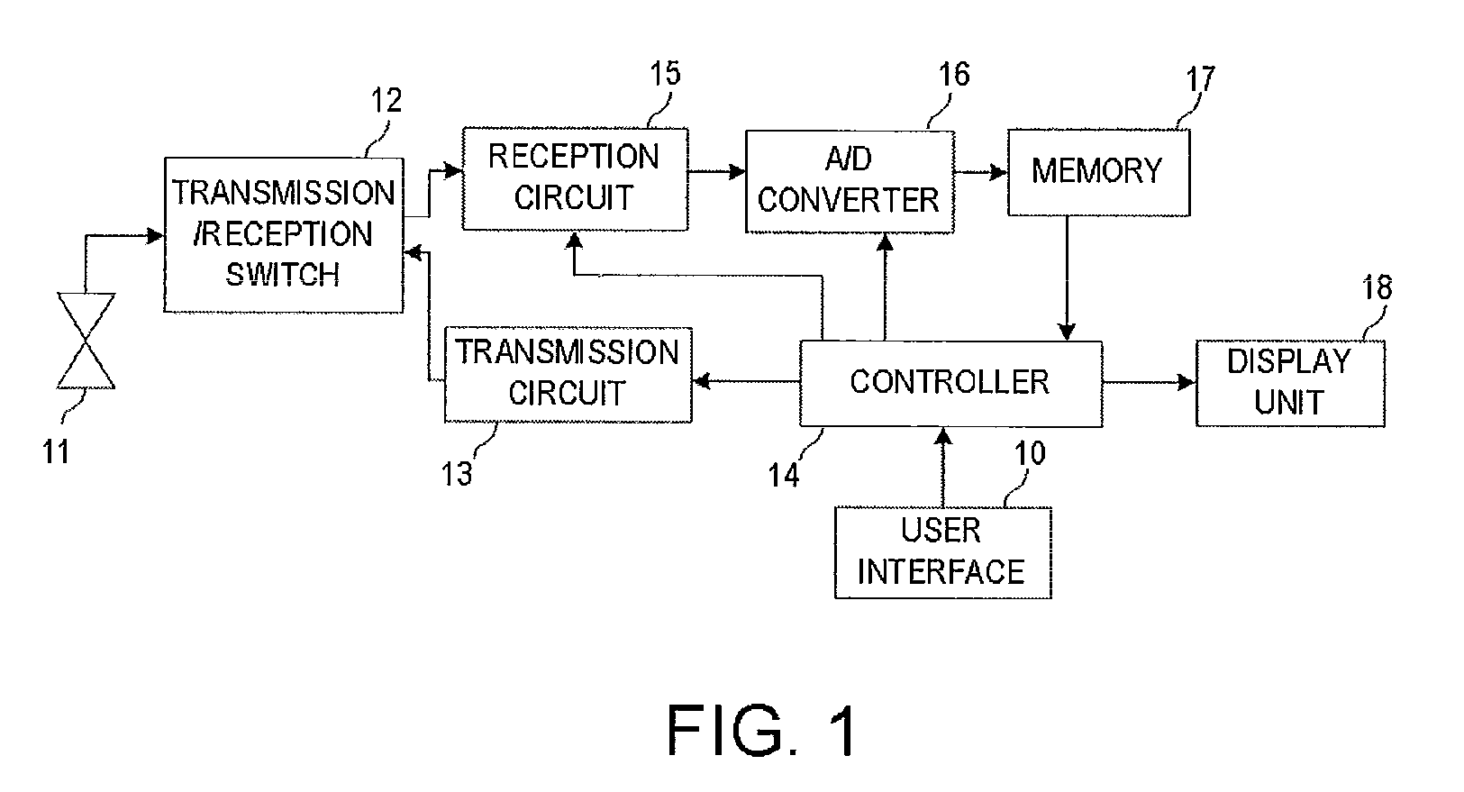
[0024]FIG. 1 is a block diagram showing a configuration of a fish finder according to one embodiment of a detection device of the present invention. In this embodiment, the fish finder includes a user interface 10, a transducer 11, a transmission / reception switch 12, a transmission circuit 13, a controller 14, a reception circuit 15, an A / D converter 16, a memory 17, and a display unit 18.

[0025]The controller 14 controls a fish finder exhaustively, and sets a transmitting cycle and a detection range of the transmission circuit 13 in response to an instruction input from the user interface 10. The controller 14 sets a cycle of corresponding sampling pulses to the A / D converter 16, writes it into the memory 17, generates a read-out clock and an address, and outputs reception data (echo data) which is used for indication on the display unit 18. The display unit 18 displays the echo data where a vertical axis of a screen is used as a depth direction and a horizontal axis as a time direc...


PUM


Abstract

This disclosure provides a device, which includes a transceiver for outputting a reception signal according to an echo intensity of a transmission signal, a reception signal monitoring module for monitoring an intensity of the reception signal based on a saturation condition, and a transmitting condition setting module for controlling a transmitting power according to the intensity of the reception signal monitored by the reception signal monitoring module.

Description

CROSS-REFERENCE TO RELATED APPLICATION(S)[0001]The application claims priority under 35 U.S.C. §119 to Japanese Patent Application No. 2010-270498, which was filed on Dec. 3, 2010, the entire disclosure of which is hereby incorporated by reference.TECHNICAL FIELD[0002]This invention relates to a detection device, such as a radar and a fish finder, and a method and a program using the features of the device.BACKGROUND OF THE INVENTION[0003]Conventionally, a detection device, such as a radar, as shown in JP09-068571A, performs a pulse compression in order to improve resolution and a signal to noise (S / N) ratio.[0004]In such a pulse compression, in order to suppress range side lobes, an envelope is weighted by applying a window function to transmission signals. However, when a reception signal is saturated, information on the envelope becomes no longer normal, and an appropriate pulse compression may be unable to be performed. In order not to saturate the reception signal, a technique ...

Claims


Application Information

Patent Timeline
Patent Type & Authority Patents(United States)
IPC IPC(8): G01S13/89G01S7/52G01S13/00G01S7/524G01S15/10G01S15/96
CPCG01S15/96G01S7/52004G01S7/524G01S15/104
Inventor MISONOO, SATOSHIASADA, YASUNOBU
Owner FURUNO ELECTRIC CO LTD
Why Eureka
Try Eureka