
Plasma actuators for drag reduction on wings, nacelles and/or fuselage of vertical take-off and landing aircraft

a technology of plasma actuators and actuators, which is applied in the direction of automatic actuation, air-flow influencers, machines/engines, etc., can solve the problems of increased fuel consumption, reduced travel speed and/or range, and aircraft carrying capacity, and achieves the effect of reducing airflow separation

Active Publication Date: 2010-09-09
UNIV OF NOTRE DAME DU LAC
View PDF14 Cites 30 Cited by
  • Summary
  • Abstract
  • Description
  • Claims
  • Application Information

AI Technical Summary

Benefits of technology

[0009]According to an aspect of the invention, an aircraft includes a surface over which an airflow passes. A plasma actuator is configured to generate a plasma above / at the surface, the plasma coupling a directed momentum into the air surrounding the surface to reduce separation of the airflow from the surface.

Problems solved by technology

The separation of the airflow from the surface may result in increased fuel consumption, reductions and / or limitations on travel speed and / or range, and the carrying capacity of the aircraft.
The voice coil based actuators or piezoelectric actuators added weight and expense to the aircraft from the slot, actuators and wires.
It was also difficult to retrofit the voice coil based actuators or piezoelectric actuators to existing aircraft.
To generate pulsating jets of air required a vibrating membrane of some construction which results in airframe noise and vibration in addition to the volume requirement inside the lifting elements.

Method used


Image

  • Plasma actuators for drag reduction on wings, nacelles and/or fuselage of vertical take-off and landing aircraft
  • Plasma actuators for drag reduction on wings, nacelles and/or fuselage of vertical take-off and landing aircraft
  • Plasma actuators for drag reduction on wings, nacelles and/or fuselage of vertical take-off and landing aircraft

Examples


Embodiment Construction

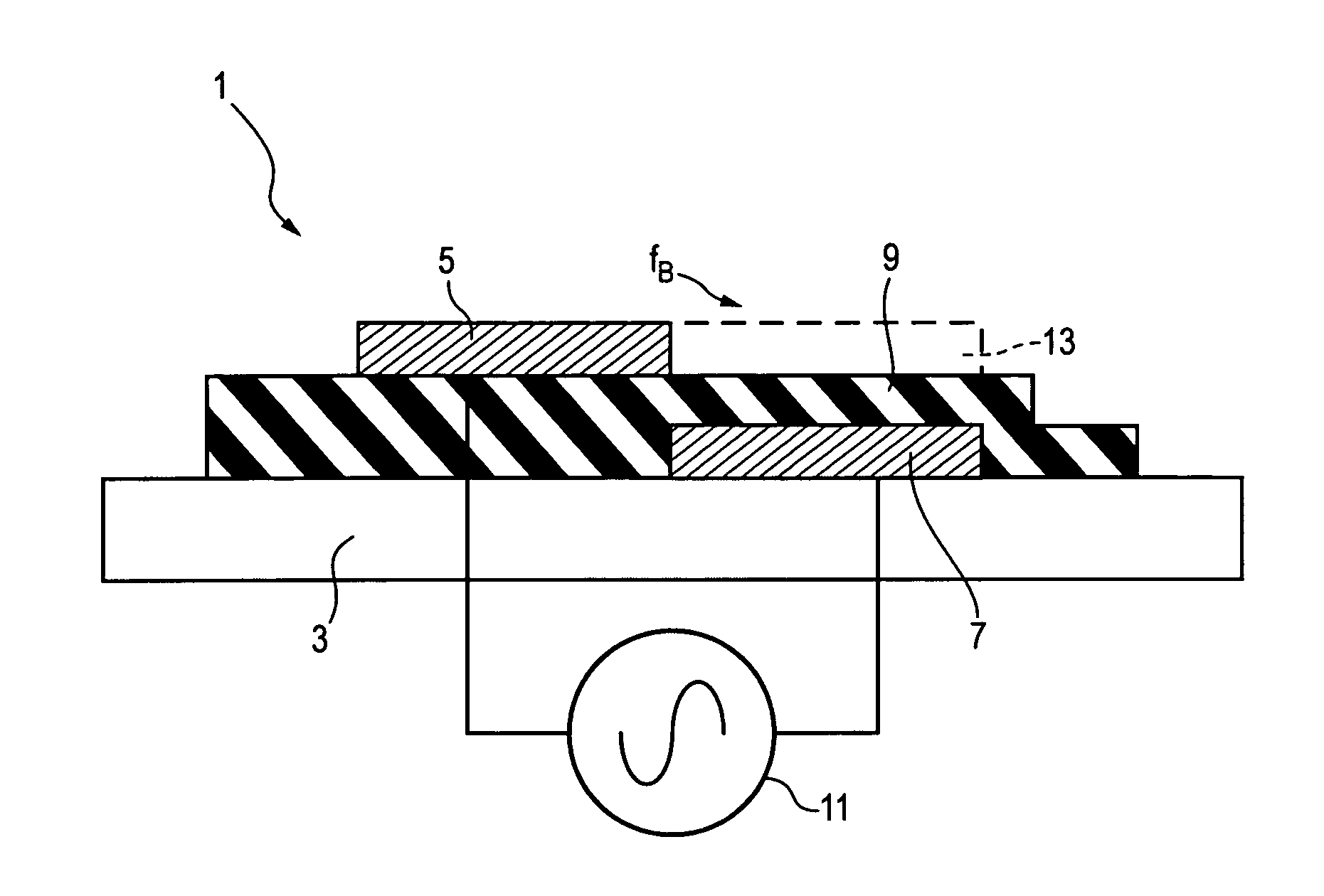
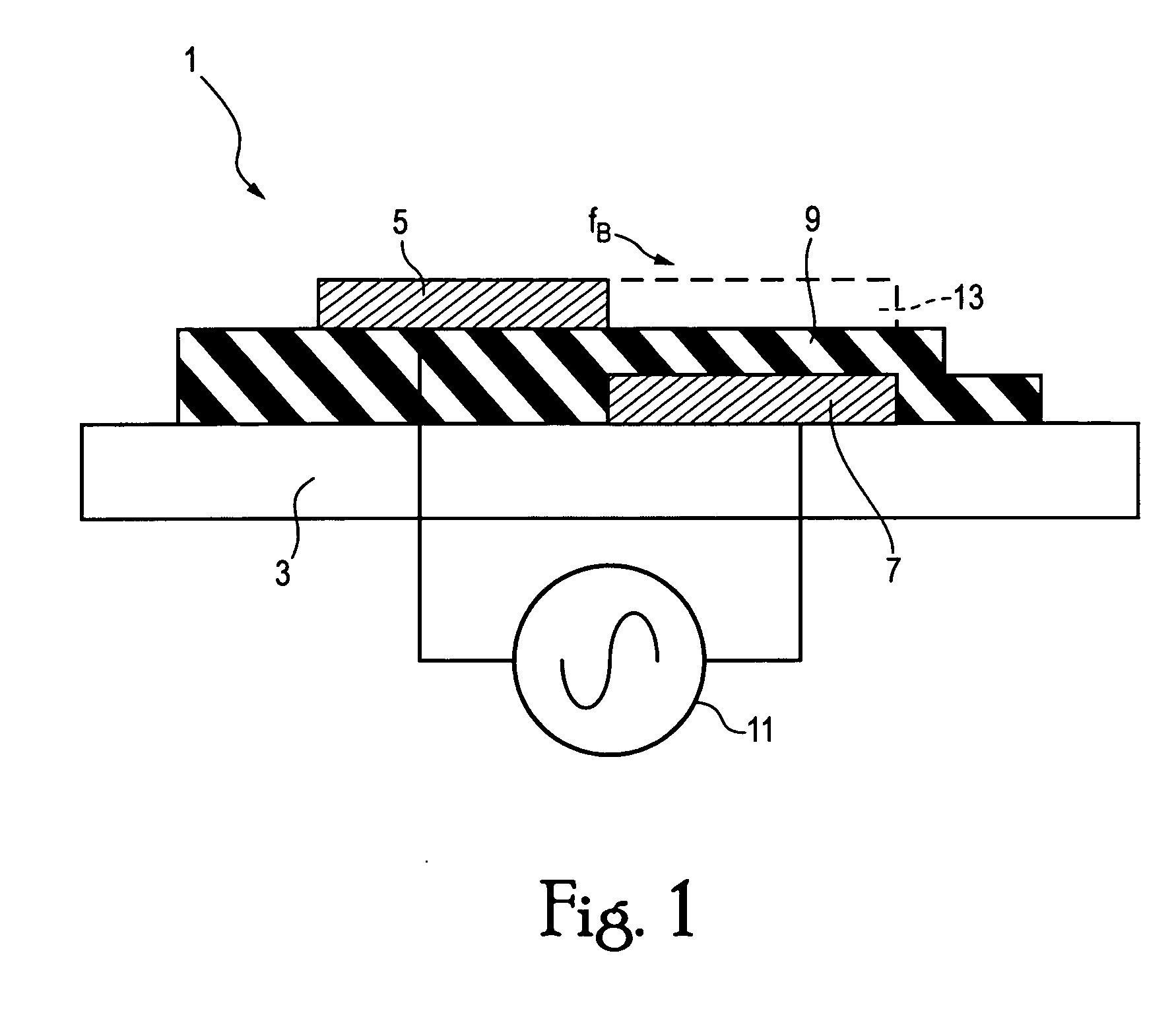
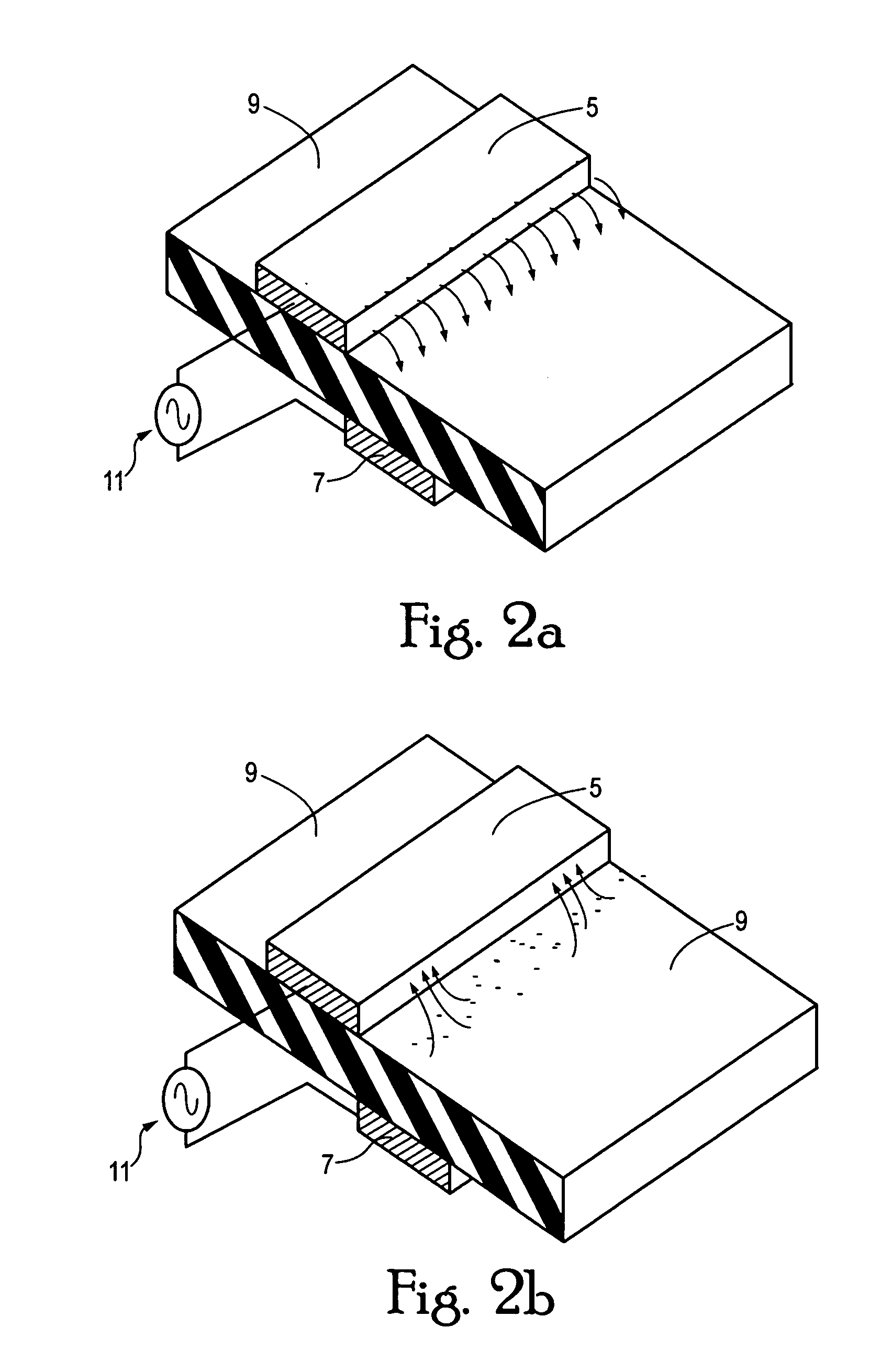
[0051]Referring to FIG. 1, a single-dielectric barrier discharge plasma actuator 1 is attached to a surface 3 of an VTOL aircraft. The actuator 1 may be attached to the surface 3 in a region in which airflow separates from the surface 3. The plasma actuator 1 includes a exposed electrode 5, a covered, insulated electrode 7 and a dielectric 9. An alternating current (AC) voltage source 11 is connected between the electrodes 5 and 7. Although the actuator 1 is shown in FIG. 1 as extending from the surface 3, it should be appreciated that the actuator 1 may be provided in a recess in the surface 3 so as to be partially or completely flush with the surface 3. The electrodes 5 and 7 may be formed of conductive material, for example copper foil. The dielectric 9 may be formed of an electrically insulating material, for example KAPTON® polyimide tape. The thickness of the dielectric is dependent on the maximum voltage that will be applied to the plasma actuator 1. Polyimide tape is thin an...


PUM


Abstract

An aircraft includes a surface over which an airflow passes. A plasma actuator is configured to generate a plasma above the surface, the plasma coupling a directed momentum into the air surrounding the surface to reduce separation of the airflow from the surface. A method of reducing separation of an airflow from a surface of an aircraft includes generating a plasma in air surrounding the surface at a position where the airflow would separate from the surface in the absence of the plasma.

Description

CROSS REFERENCE TO RELATED APPLICATION[0001]This application claims priority to U.S. Application 60 / 726,648, filed Oct. 17, 2005, the entire contents of which are incorporated herein by reference.STATEMENT REGARDING FEDERALLY SPONSORED RESEARCH[0002]The present invention was developed in accordance with Agreement DABT 63-00-3-001 between Bell Helicopter Textron Inc. and the Defense Advanced Research Projects Agency.BACKGROUND OF THE INVENTION[0003]1. Field of the Invention[0004]The present invention relates to the use of single-dielectric barrier discharge plasma actuators for drag reduction on wings, nacelles and / or fuselage of aerodynamic vehicles designed for vertical take-off and landing (VTOL).[0005]2. Description of the Related Art[0006]Aircraft may include surfaces that have regions where the airflow over the surface is not able to follow the contour of the surface. The airflow is said to “separate” from the surface in these regions. The separation of the airflow from the sur...

Claims


Application Information

Patent Timeline
Patent Type & Authority Applications(United States)
IPC IPC(8): B64C21/00
CPCB64C23/005F05D2270/172B64C2230/12Y02T50/166F15D1/12H05H1/2439Y02T50/10B64C23/00B64C21/00
Inventor WOOD, TOMMIE L.CORKE, THOMAS C.POST, MARTIQUA
Owner UNIV OF NOTRE DAME DU LAC
Learn More