
Heavy-load radial tire

Inactive Publication Date: 2010-09-09
SUMITOMO RUBBER IND LTD
View PDF2 Cites 18 Cited by
  • Summary
  • Abstract
  • Description
  • Claims
  • Application Information

AI Technical Summary

Benefits of technology

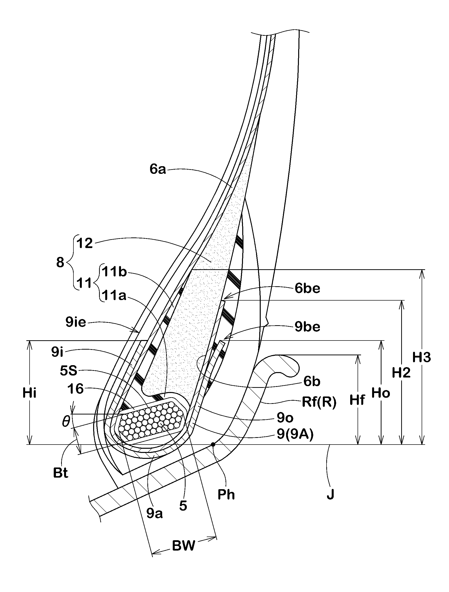
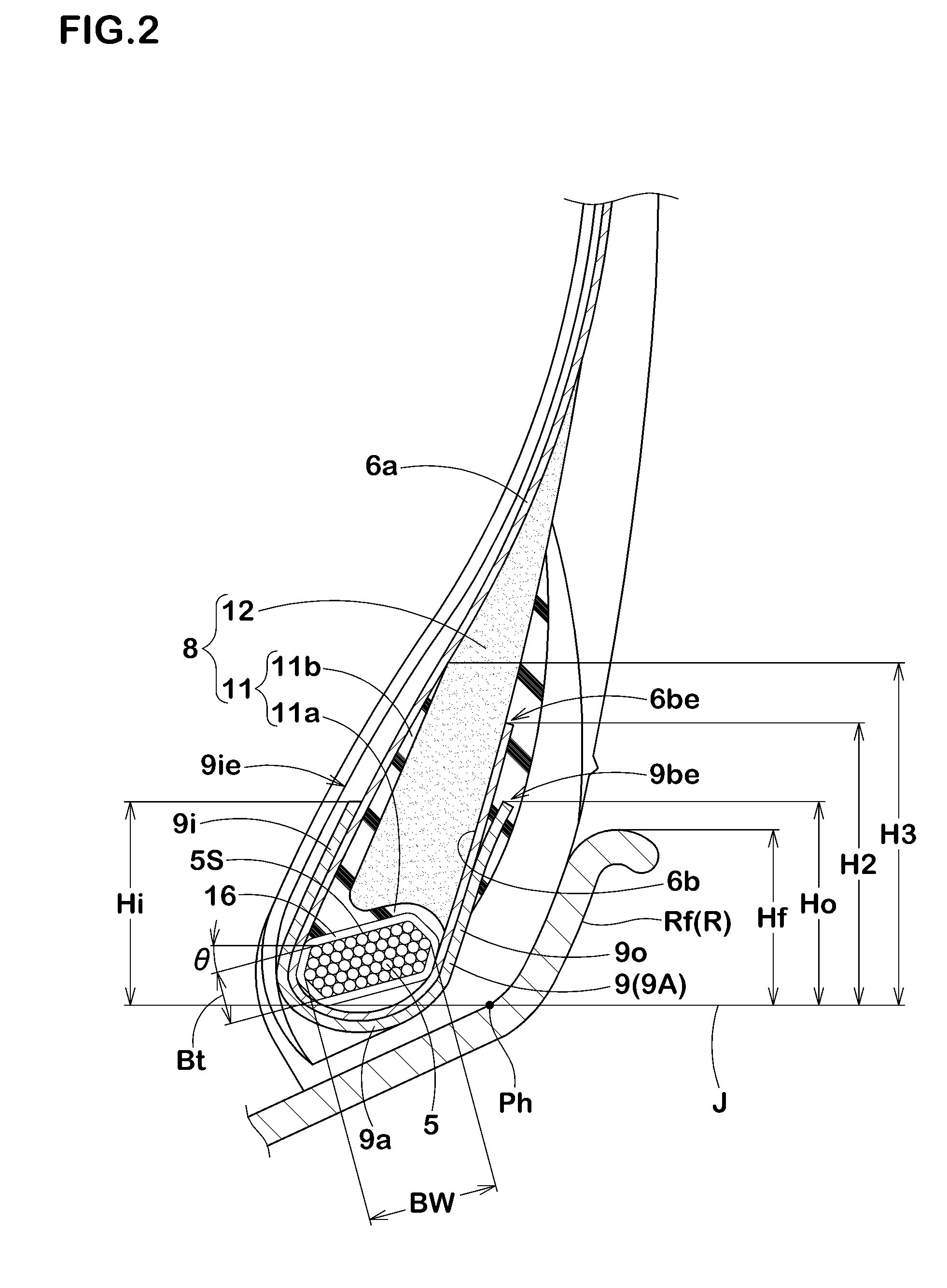
[0027]Meanwhile, a sufficient restraining force of the bead core is secured by making the core width Bw of the bead core as high as 0.70 to 0.80 times the bead bottom width BL. Further, the bead core is moved toward the axially inner side to make the distance W1, which is oriented in parallel to the radially outer surface of the bead core and ranges from the bead heal point to the axially innermost end of the bead core, as high as 0.92 to 1.08 times the bead bottom width BL. That is, the bead core is relatively spaced apart from the rim flange, thereby effectively inhibiting the axially outward deformation of the bead with the rim flange serving as supporting point. Relatively spacing the bead core apart from the rim flange increases the degree of axially outward incline of the profile of the ply main portion before deformed, thus making the profile close to that during bead deformation. These advantageous effects are combined to effectively inhibit cord loosening at the outer end of the ply turnup portion, thereby improving bead durability.
are combined to effectively inhibit cord loosening at the outer end of the ply turnup portion, thereby improving bead durability.

Problems solved by technology

This involves substantial movement of the bead apex rubber, which in turn causes shearing strain between the bead apex rubber and the ply turnup portion.
Repeated occurrence of shearing strain causes cord loosening at the outermost end of the ply main portion, resulting in bead damage.
Bead damage is likely to occur especially on heavy-load radial tires, such as for trucks and buses, which involve heavy load.
However, the L-shaped cross section of the lower apex portion b1 reduces rigidity, which increases the deformation quantity of the profile of the ply main portion while the vehicle is running

Method used


Image

  • Heavy-load radial tire
  • Heavy-load radial tire
  • Heavy-load radial tire

Examples


Embodiment Construction

[0032]The following detailed description is made with reference to the figures.

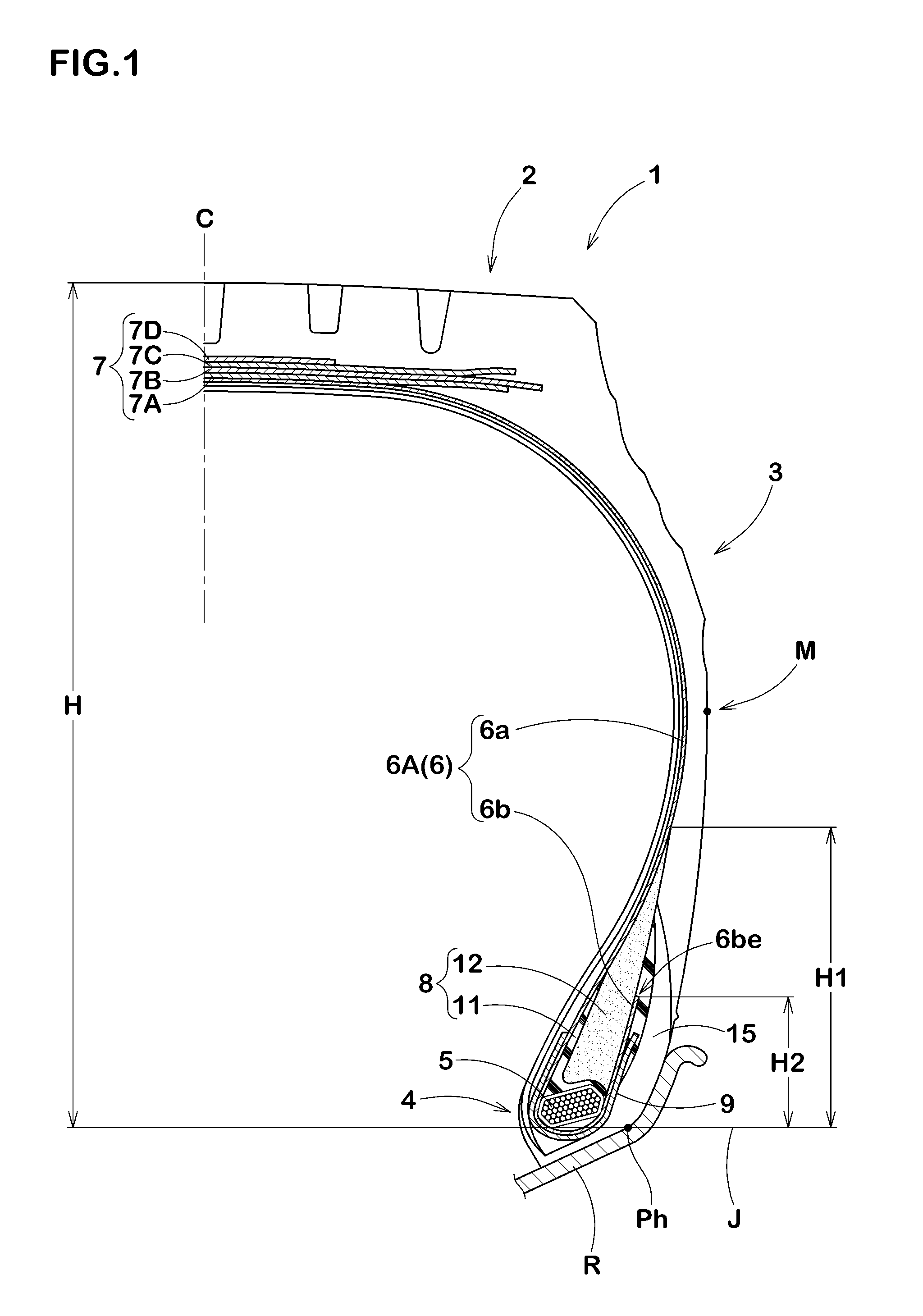
[0033]Referring to FIG. 1, a heavy-load radial tire 1 according to the present embodiment is a tubeless tire mounted on a 15°-tapered rim R and includes: a toroidal carcass 6 that extends from a tread portion 2 through a side wall portion 3 to a bead core 5 of a bead section 4; a belt layer 7 disposed in the tread portion 2 and on the radially outer side of the carcass 6; a bead apex rubber 8 that extends radially outwardly from the bead core 5 in a tapered manner; and a bead reinforcing cord layer 9 disposed on the bead section 4.

[0034]The carcass 6 is formed of a carcass ply 6A having steel carcass cords aligned at an angle of 80 to 90° relative to a tire equator C. The carcass ply 6A includes a ply main portion 6a extending between bead cores 5. Provided at each end of the ply main portion 6a is a ply turnup portion 6b integral with the ply main portion 6a and turned up from the axially inner side to t...


PUM


Abstract

A heavy-load radial tire includes a bead apex rubber 8 composed of a high-elastic lower apex portion 11 and a low-elastic upper apex portion 12. The lower apex portion 11 has an L-shaped cross section composed of a bottom piece portion 11a disposed along the radially outer surface of a bead core 5 and a standing piece portion 11b standing from the axially inner end of the bottom piece portion 11a and radially outwardly extending along a ply main portion 6a of a carcass 6. At an outer end position P1 of a ply turnup portion 6b, the upper apex portion 12 has a thickness T1s of 0.50 to 0.75 times a core width Bw of the bead core 5. At an outer end position P2 of an outer wound-up portion 9o of a bead reinforcing cord layer 9, the upper apex portion 12 has a thickness T2s of 0.57 to 0.90 times the core width Bw. The core width Bw is 0.68 to 0.80 times a bead bottom width BL. A distance W1 oriented in parallel to an outer surface 5S of the bead core 5 and ranging from a bead heal point Ph to an axially innermost end 5e of the bead core 5 is 0.92 to 1.08 times the bead bottom width BL.

Description

BACKGROUND OF THE INVENTION[0001]1. Technical Field[0002]The present invention relates to a heavy-load radial tire possessing improved bead durability.[0003]2. Related Art[0004]Pneumatic tires, when heavily loaded, have the ply main portions of their carcasses fall toward the rim. This involves substantial movement of the bead apex rubber, which in turn causes shearing strain between the bead apex rubber and the ply turnup portion. Repeated occurrence of shearing strain causes cord loosening at the outermost end of the ply main portion, resulting in bead damage. Bead damage is likely to occur especially on heavy-load radial tires, such as for trucks and buses, which involve heavy load.[0005]In view of this, conventional heavy-load radial tires commonly use a two-layer structure as shown in FIG. 4A, where a bead apex rubber b disposed between a ply main portion a1 and a ply turnup portion a2 of the carcass is divided into a lower apex portion b1 of high-elastic rubber disposed on a r...

Claims


Application Information

Patent Timeline
IPC IPC(8): B60C15/06
CPCB60C15/04B60C15/06Y10T152/10837B60C2015/0625Y10T152/10819B60C2200/06B60C15/0607B60C2015/009B60C2015/0617
Inventor MARUOKA, KIYOTO
Owner SUMITOMO RUBBER IND LTD
Learn More