
High speed quantum efficiency measurement apparatus utilizing solid state lightsource

a quantum efficiency and measurement apparatus technology, applied in radiation measurement, optical radiation measurement, spectral modifiers, etc., can solve the problems of high cost, inefficient filter design, and low peak transmission (50%), and achieve the effect of quantum efficiency

Inactive Publication Date: 2010-09-02
TAU SCI CORP
View PDF3 Cites 55 Cited by
  • Summary
  • Abstract
  • Description
  • Claims
  • Application Information

AI Technical Summary

Benefits of technology

[0014]The present invention provides a high-speed Quantum Efficiency (QE) measurement device that includes at least one device under test (DUT), at least one conditioned light source having at least one filtered LED with a less than 50 nm bandwidth, where a portion of the conditioned light source is monitored by light source monitoring elements having at least one collection optic and at least one photo detector. The high-speed QE measurement device further includes delivery optics disposed to direct the conditioned light source to the DUT, a controller that drives the conditioned light source in a time dependent operation, where a response by each DUT from the conditioned light source is uniquely identified, and at least one reflectance measurement assembly having at least one reflectance collection opt

Problems solved by technology

. . ) from reaching the output slit, and also leak a measurable amount of broadband stray light that can not readily be removed by filters.
Interference filter-based systems offer good stray light rejection, but use multi-layer dielectric films that eventually degrade due to direct exposure to the high intensity, and UV-containing, broadband lightsource.
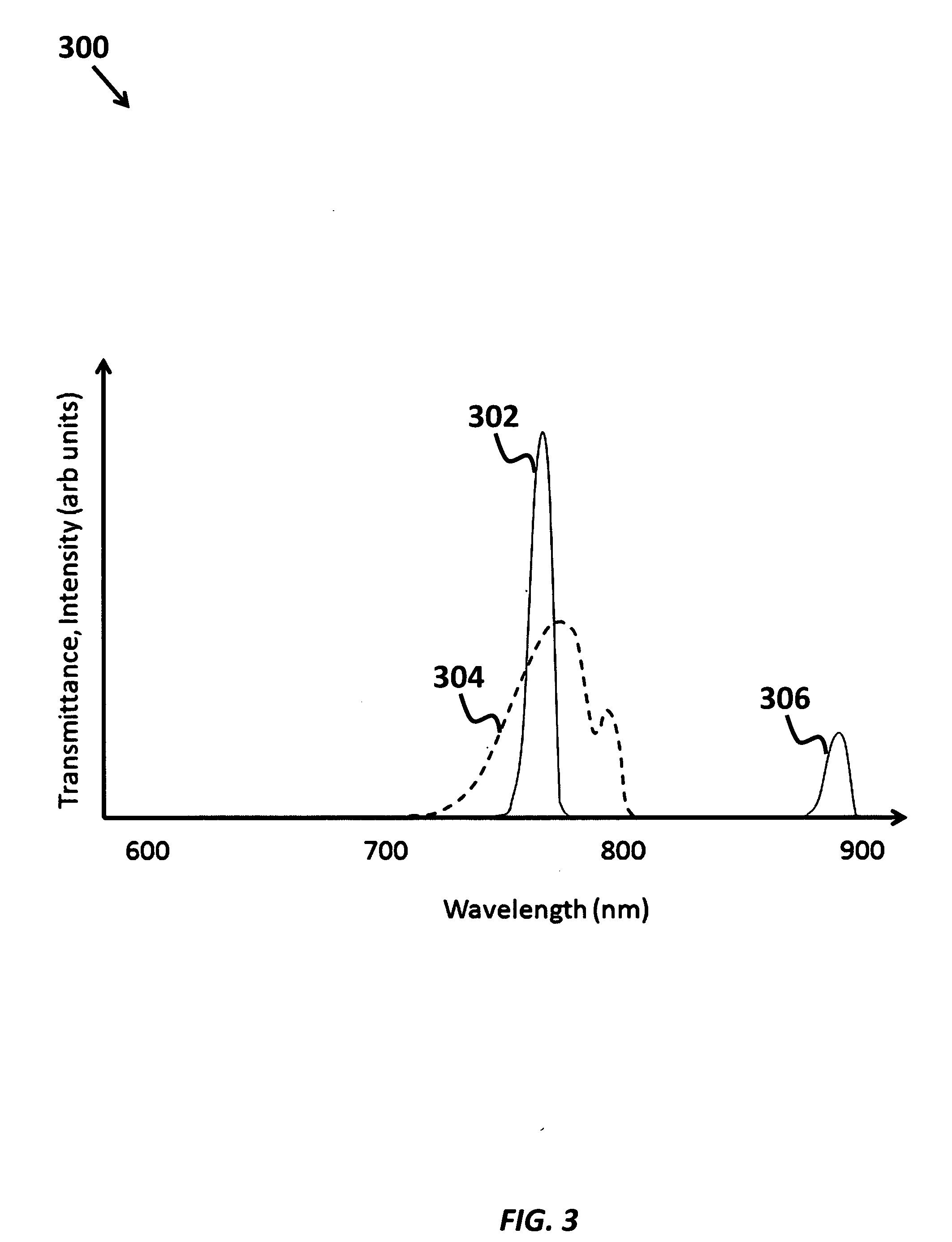
Filter designs with wide rejection bands (required for use with a broadband light source) tend to be both inefficient (with peak transmission<50%) and expensive.
Traditional filter designs with wide rejection bands suffer significant increase in losses as they are tuned via tilting.
Because conventional sources emit light with a poor etendue, a significant throughput penalty must be suffered when integrating such sources with a monochromator.
This throughput penalty is in addition to the inherent losses associated with selecting a small portion of the lamp spectrum, and with the internal inefficiencies of the monochromator itself.
Hence, conventional sources cannot deliver spectrally selected light efficiently to a QE measuring system.
This is the origin of the very high power consumption that is common to existing systems.
Additionally, the unstable light output (both short term and long term) of conventional light sources necessitates frequent calibrations and bulb replacement.
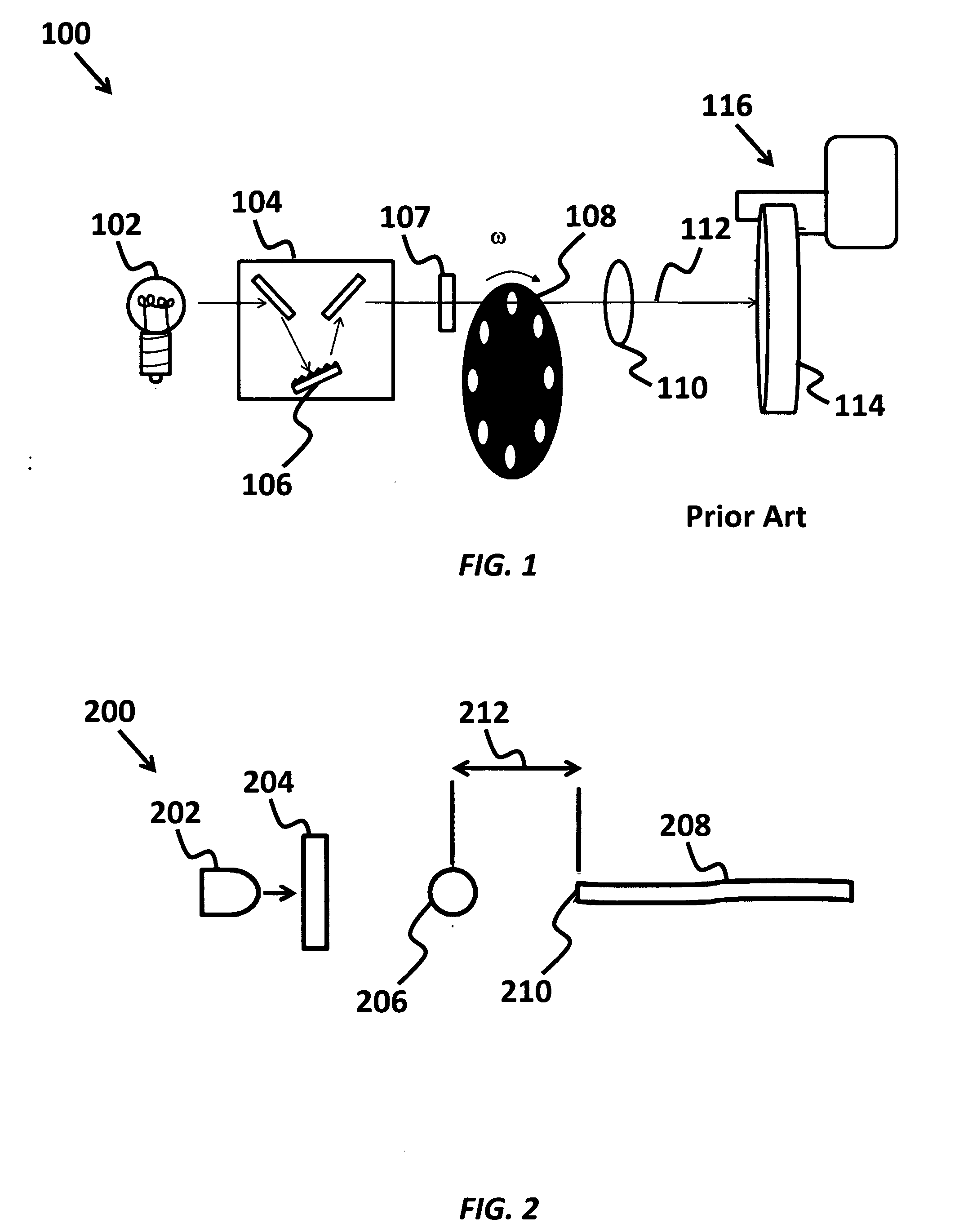
In both monochromator and interference filter systems, a basic limitation is the speed with which the system can scan through a set of wavelengths.
Mechanical motion must occur to step from one wavelength to the next, and this limits the practical throughput of the system.
With this measurement overhead, full spectra often take 5-10 minutes to cover the necessary wavelength range with sufficient resolution.
This required mechanical motion also increases the cost and complexity of the instrument and makes it less suitable for a manufacturing environment.
The long measurement time of conventional QE systems prevents them from effectively being used in a mapping mode (10's to 1000's of data points per sample) to study localized or spatially varying effects.
Also, the poor etendue of the conventional source sets a minimum practical measurement area, such that any reduction in measurement area below this value creates a further tradeoff of spatial resolution and measurement speed.
Though this resulted in a reduction in the determination time, the resulting QE measurement included significant margins of error, due to poor spectral control of the LED light source and because light reflected, scattered or transmitted by the DUT was not measured and accounted for.

Method used


Image

  • High speed quantum efficiency measurement apparatus utilizing solid state lightsource
  • High speed quantum efficiency measurement apparatus utilizing solid state lightsource
  • High speed quantum efficiency measurement apparatus utilizing solid state lightsource

Examples


Embodiment Construction

[0043]Although the following detailed description contains many specifics for the purposes of illustration, anyone of ordinary skill in the art will readily appreciate that many variations and alterations to the following exemplary details are within the scope of the invention. Accordingly, the following preferred embodiment of the invention is set forth without any loss of generality to, and without imposing limitations upon, the claimed invention.

[0044]According to the current invention, the QE measurement applies also to the measurement of Responsivity or SR via a simple conversion of units. The current invention provides a high-speed quantum efficiency (QE) measurement device. In one aspect, the invention uses LED light sources, where commonly available LED's have LED output ranges that span from 300 nm to 1600 nm with approximately 10-50 nm spacing. The high spectral brightness (power per unit bandwidth per unit area per unit solid-angle) of LED's compares favorably with other ...


PUM


Abstract

The present invention provides a high-speed Quantum Efficiency (QE) measurement device that includes at least one device under test (DUT), at least one conditioned light source with a less than 50 nm bandwidth, where a portion of the conditioned light source is monitored. Delivery optics are provided to direct the conditioned light to the DUT, a controller drives the conditioned light source in a time dependent operation, and at least one reflectance measurement assembly receives a portion of the conditioned light reflected from the DUT. A time-resolved measurement device includes a current measurement device and / or a voltage measurement device disposed to resolve a current and / or voltage generated in the DUT by each conditioned light source, where a sufficiently programmed computer determines and outputs a QE value for each DUT according to an incident intensity of at least one wavelength of from the conditioned light source and the time-resolved measurement.

Description

CROSS-REFERENCE TO RELATED APPLICATIONS[0001]This application is cross-referenced to and claims the benefit from U.S. Provisional Application 61 / 156,532 filed Mar. 1, 2009, and which are hereby incorporated by reference.FIELD OF THE INVENTION[0002]The invention relates to measurement of the conversion of light energy to electrical energy. More specifically, the invention relates to a high-speed time-resolved quantum efficiency measurement device from a conditioned light source.BACKGROUND[0003]Photodiodes and solar cells are often characterized by quantum efficiency (QE) and responsivity to measure the optical-to-electrical conversion efficiency of the device. Quantum Efficiency is expressed in units of outgoing electrons per incident photon, while Responsivity is expressed in units of outgoing current per incident Watt (A / W). Further, spectral response (SR) is a measure of the device conversion efficiency as a function of incident photon wavelength or optical frequency. Spectral res...

Claims


Application Information

Patent Timeline
IPC IPC(8): G01J1/44G01N21/55
CPCG01N21/55G01N21/59H02S50/10G01N2201/0627G01N2201/0691G01N2021/556Y02E10/50G01R19/165G01N21/63
Inventor ARBORE, MARK A.KLEIN, DAVID L.VASILYEV, LEONID A.SCHMIDT, JOHN M.HUDSON, JAMES E.HORNER, GREGORY S.
Owner TAU SCI CORP
Learn More