Fuel tank opening-closing device

a technology for opening and closing the fuel tank, which is applied in the direction of liquid handling, packaging goods, transportation and packaging, etc., can solve the problems of reducing the sealing function or degrading the risk of the flapper valve, and achieve the effect of facilitating discharge and easing the distance of the gap

Inactive Publication Date: 2010-09-02
TOYODA GOSEI CO LTD
View PDF13 Cites 58 Cited by
  • Summary
  • Abstract
  • Description
  • Claims
  • Application Information

AI Technical Summary

Benefits of technology

[0007]An advantage of some aspects of the invention is to provide a fuel tank opening-closing device of simple design adapted to prevent diminished or degraded sealing function by the flapper valve.
[0010]Because the cover body of the cover covers the outside peripheral portion and the vicinity of the opening of the filler port from above, water resistance is afforded even during high-pressure washing, and additionally it will be harder for grime and the like to enter so that the sealing function of the flap valve mechanism will not be diminished or degraded. Moreover, the cover body of the cover, rather than being a plate member covering the entire face above the opening-closing member, instead covers only the top of the gap along the entire peripheral edge portion of the opening-closing member, so the design is simpler.
[0015]In the opening-closing member of the flap valve mechanism there has been formed a frangible region having a notch formed between the locking part and a location sealed by a gasket, in the locked part which engages the locking member. When the locked part has been subjected to strong outside force exerted thereon by the introductory push parts through the locking member in response to outside force bearing on the tank opening forming member, the frangible region will break in a section thereof with the notch as the point of origin. Owing to the frangible region, only the locked part will break when subjected to such strong outside force through the locking member, and thus the gasket will be maintained in sealed condition by the opening-closing member. Because the frangible region consists of a notch that has been formed at the bottom of a recess in the locked part, in response to force exerted in a direction tending to expand the notch it will function as the point of origin of breakage so that the breaking load will be low; whereas in response to force received from the fueling nozzle by the push members of the opening-closing member, which is force in a direction tending to constrict the width of the notch, it will readily deform elastically so that the breaking load will be high. Consequently, the locked part will not break when the opening-closing member is subjected to force from the fueling nozzle, and the sealing function of the gasket will not be impaired.
[0016]In yet another arrangement according to a sixth mode, the locked part is a recess adapted to engage the locking member which has been formed in the side portion of the opening-closing member, and the notch has been formed at the bottom of the recess by reducing the thickness of the opening-closing member about the entire circumference of the opening-closing member. Such a notch can be easily designed so that the first breaking load will be greater than the second breaking load to readily achieve an arrangement for reducing mechanical strength in the locked part only.
[0021]In yet another arrangement according to a tenth mode, the nozzle detection mechanism has resilient support pieces fastening the introductory push parts at one end thereof in cantilever fashion to the tank opening forming member and adapted to produce spring force towards the direction of return to the original position through movement of the introductory push parts; the resilient support pieces have a conductive member fabricated of electrically conductive material and disposed facing the tank opening forming member; and the conductive member has discharge protrusions protruding out towards the tank opening forming member. Through this arrangement, when the resilient support piece has undergone elastic deformation, the discharge protrusions, with the resilient support piece as the fulcrum point, will likewise move closer to the opening-defining member, thus providing more dependable contact with the opening-defining member, as well as compensating for dimensional variations caused by deformation during molding or the like, so as to provide more dependable grounding action.
[0024]The discharge protrusions will produce the same action regardless of whether they projects out from either the introductory push parts or the tank opening forming member towards the other, and may be selected appropriately depending on these arrangements. The discharge protrusions afford ease of setting the distance of the gap between the two, and can facilitate discharge along the path of electrical current flow through the air in the gap.

Problems solved by technology

However, water and foreign matter may infiltrate from the outside through this gap at the rim of the filler port or become deposited therein, and the associated risk of diminished or degraded sealing function by the flapper valve proved to be a problem.

Method used


Image

  • Fuel tank opening-closing device
  • Fuel tank opening-closing device
  • Fuel tank opening-closing device

Examples


first embodiment

A. First Embodiment

[0050](1) General Configuration of Fuel Tank Closure System

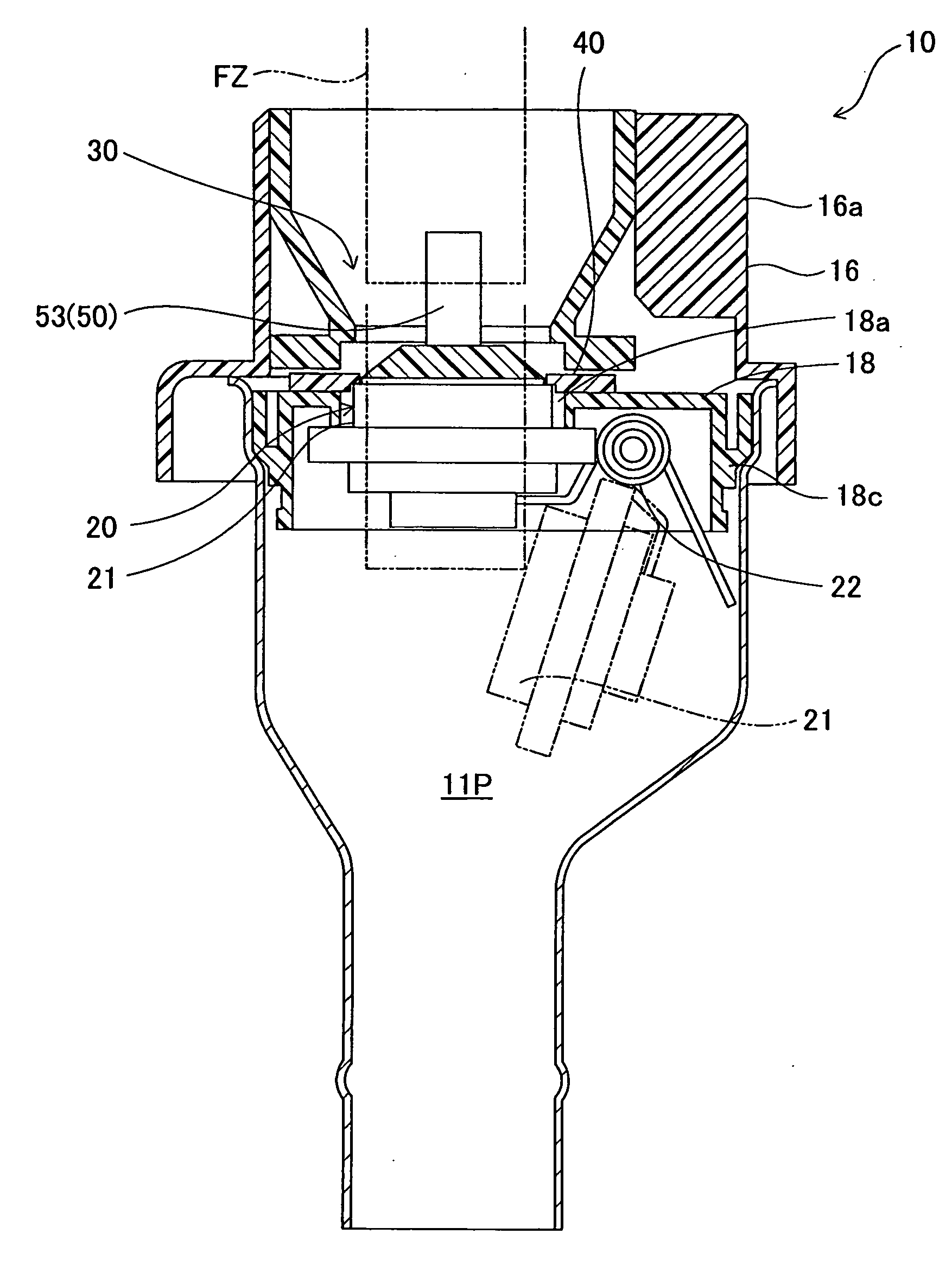
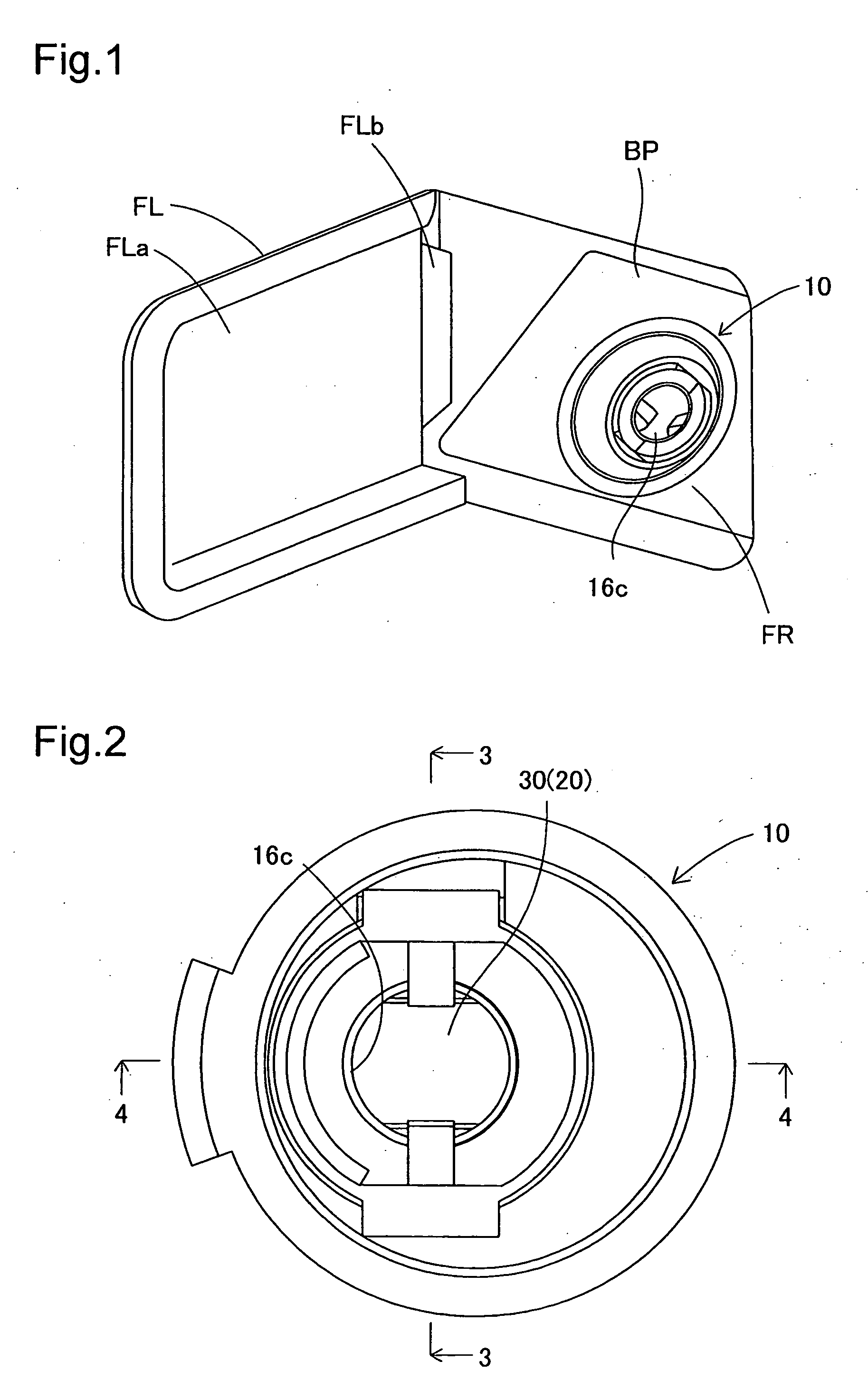
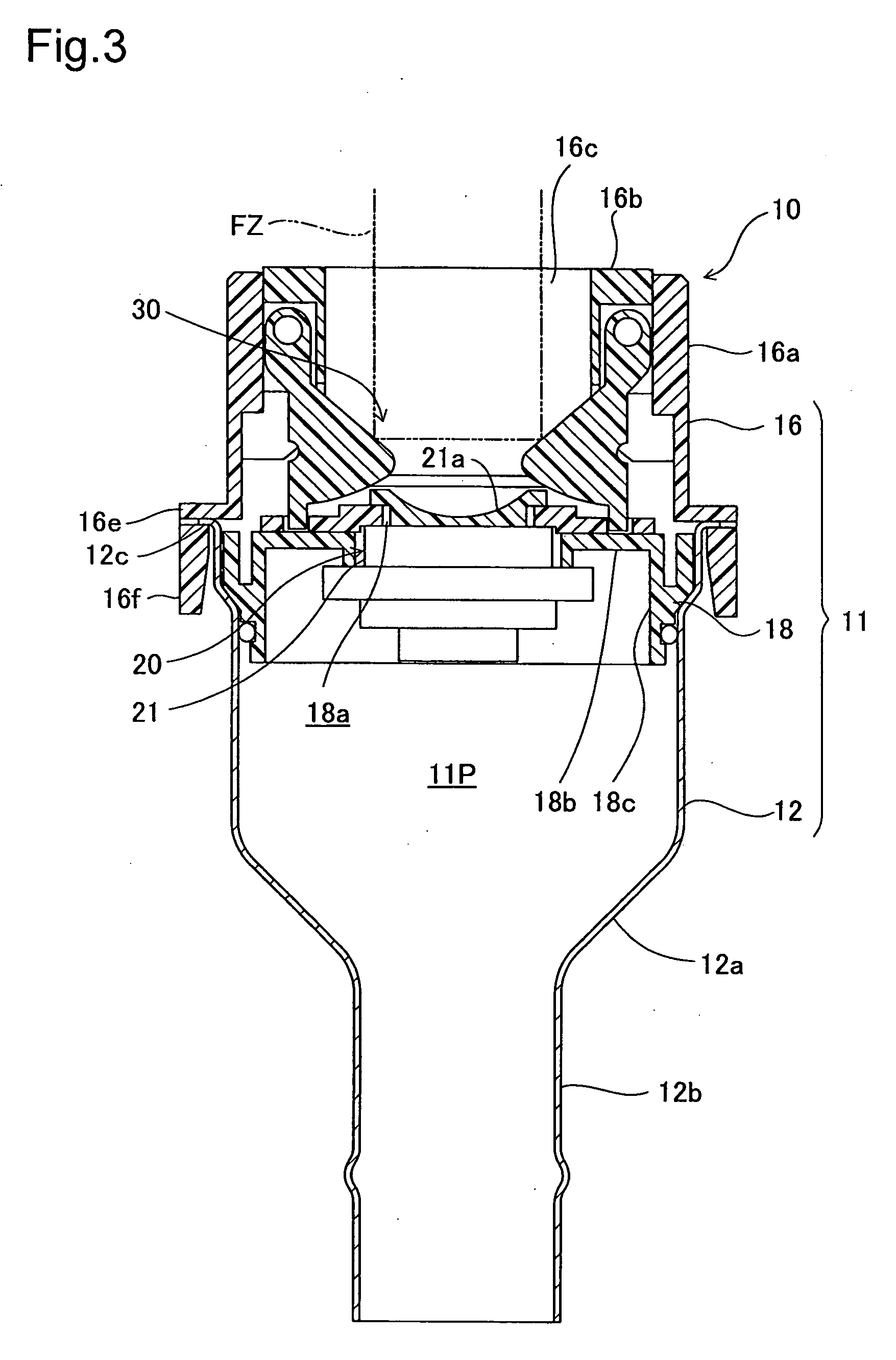
[0051]FIG. 1 is a perspective view depicting a rear section of an automobile equipped with a diesel engine according a first embodiment of the present invention, shown with the fuel cover open. A fuel cover FL for supplying a fuel (diesel) is reclosably supported at the rear section of the body of the automobile. The fuel cover FL has a cover body FLa conforming to the contours of the exterior panels of the vehicle and reclosably supported on a vehicle exterior panel via a hinge FLb. The space revealed by the opened fuel cover FL functions as a fueling bay FR, and a fuel tank opening-closing device 10 supported on a base plate BP has been arranged inside the fueling bay FR. The fuel tank opening-closing device 10 is a mechanism whereby fuel can be supplied from a fueling nozzle without using a fuel cap, and has been designed so that once the fuel cover FL has been opened, fuel can be supplied from a fuelin...

second embodiment

B. Second Embodiment

[0080]FIG. 10 is an exploded perspective view showing a fuel tank opening-closing device 10B according to a second embodiment. A feature of the present embodiment is the arrangement of a nozzle detection mechanism 50B for detecting insertion of a fueling nozzle. Specifically, a nozzle detection member 51B of this nozzle detection mechanism 50B includes introductory push parts 53B disposed to both sides of the fuel passage 11P; resilient support pieces 56B linked at one end thereof to the introductory push parts 53B so as to extend upward therefrom; and a fastened linking arm 57B that links the resilient support pieces 56B in their upper portion. The fastened linking arm 57B is a band-shaped member of semicircular form fastened to the opening-defining member. With this arrangement, when the introductory push parts 53B, 53B are pushed towards the perpendicular direction with respect to the direction of insertion of the fueling nozzle FZ, spring force is generated c...

third embodiment

C. Third Embodiment

[0081]FIG. 11 is a sectional view showing a fuel tank opening-closing device 10C according to a third embodiment. A feature of the present embodiment is the arrangement of a locking mechanism 60C adapted to operate in interlocked fashion in association with insertion of the fueling nozzle FZ. Specifically, locking members 61C of the locking mechanism 60 have been integrally formed with introductory push parts 53C and are designed to shuttle between a locked position at which the locking members 61C are engaged by locked parts 62C of an opening-closing member 21C, and an unlocked position at which through pushing of the introductory push parts 53C the locking members 61C have disengaged from the locked parts 62C so that the opening operation of the opening-closing member 21C becomes possible. Thus, an arrangement whereby the locking members 61C of the locking mechanism 60 shuttle between the locked position and the unlocked position with respect to the opening-clos...


PUM

PropertyMeasurementUnit
diameteraaaaaaaaaa
diameteraaaaaaaaaa
diameteraaaaaaaaaa

Abstract

A fuel tank opening-closing device includes a flap valve mechanism situated inside a tank opening forming member and having a flap valve mechanism; and an opening-closing activation mechanism adapted to selectively set the flap valve mechanism to a locked position or an unlocked position. The opening-closing activation mechanism includes a cover covering the peripheral edge portion of the opening-closing member and having a cover body produced by being split into arcuate shapes of prescribed width; a nozzle detection mechanism having introductory push parts that are adapted to receive force of motion in the insertion direction by a fueling nozzle; locking members which engage or disengage from the opening-closing member; and a locking mechanism having and adapted to move the locking members from the locked position to the unlocked position through interlocking operation with the introductory push parts.

Description

[0001]This application claims the benefit of and priority from Japanese Applications No. 2009-45315 filed Feb. 27, 2009, No. 2009-83940 filed Mar. 31, 2009, and No. 2009-83941 filed Mar. 31, 2009, the contents of which are incorporated herein by reference.BACKGROUND OF THE INVENTION[0002]1. Field of the Invention[0003]The present invention relates to a fuel tank opening-closing device having a flapper valve adapted to open through insertion force of the fueling nozzle.[0004]2. Description of the Related Art[0005]Fueling nozzles for fueling an automobile are typically dimensioned differently to distinguish those dispensing gasoline from those dispensing gasoline diesel fuel, with a gasoline nozzle having a diameter of 20 mm while a diesel nozzle has a diameter of 25 mm. One known technology relating to such a fueling system with different nozzle diameters adapted to handle different types of fuel is disclosed in U.S. Pat. No. 6,968,874. Specifically, the fueling system includes a tan...

Claims


Application Information

Patent Timeline
Patent Type & Authority Applications(United States)
IPC IPC(8): B60K15/05
CPCB60K15/04B60K2015/0483B60K2015/0429
Inventor HAGANO, HIROYUKI
Owner TOYODA GOSEI CO LTD
Why Eureka
Try Eureka