
Method and apparatus for operation of co/voc oxidation catalyst to reduce no2 formation for gas turbine

a technology of oxidation catalyst and gas turbine, which is applied in the direction of mechanical equipment, machines/engines, separation processes, etc., can solve the problems of increasing total ammonia consumption, reducing the total ammonia consumption of the system, and reducing the oxide of nitrogen present in the flue gas only with great difficulty

Active Publication Date: 2010-08-26
GENERAL ELECTRIC CO
View PDF26 Cites 53 Cited by
  • Summary
  • Abstract
  • Description
  • Claims
  • Application Information

AI Technical Summary

Benefits of technology

[0012]The emissions treatment apparatus includes, relative to a flowpath of the exhaust gases, a carbon monoxide (CO) oxidation catalyst disposed at a location in the gas turbine exhaust path adapted for limiting NO2 production from NO by the CO oxidation catalyst affected by placement at a location with an exhaust gas temperature for which the CO catalyst advantageously limits NO2 production. The emissions treatment apparatus further includes an ammonia injection apparatus (MG) disposed downsteam from the CO reduction catalyst and adapted for injecting ammonia into a flow of exhaust gases, a mixing section disposed downstream of the ammonia injection apparatus and adapted for mixing injected ammonia with the flow of exhaust gases, and a selective catalytic reduction (SCR) element disposed downsteam of the ammonia injection apparatus a...

Problems solved by technology

However, combustion controls alone may prove inadequate to satisfy these often-conflicting goals, and thus continued the improvement of post-combustion exhaust gas treatment systems is desired.
Thus, the oxides of nitrogen that are present in the flue gas can be reduced to nitrogen and water only with great difficulty.
The third reaction requires one third more ammonia to reduce NO2 than the second reaction, increasing total ammonia consumption.
Excessive temperatures may also damage the catalyst.
The oxidizing process is typically located upstream of the ammonia injection location and upstream of the reducing catalyst, because the oxidizing catalyst will also function to oxidize ammonia, which is undesirable as it decreases the amount of ammonia available for reduction of the NOx and because it produces additional NOx compounds.

Method used


Image

  • Method and apparatus for operation of co/voc oxidation catalyst to reduce no2 formation for gas turbine
  • Method and apparatus for operation of co/voc oxidation catalyst to reduce no2 formation for gas turbine
  • Method and apparatus for operation of co/voc oxidation catalyst to reduce no2 formation for gas turbine

Examples


Embodiment Construction

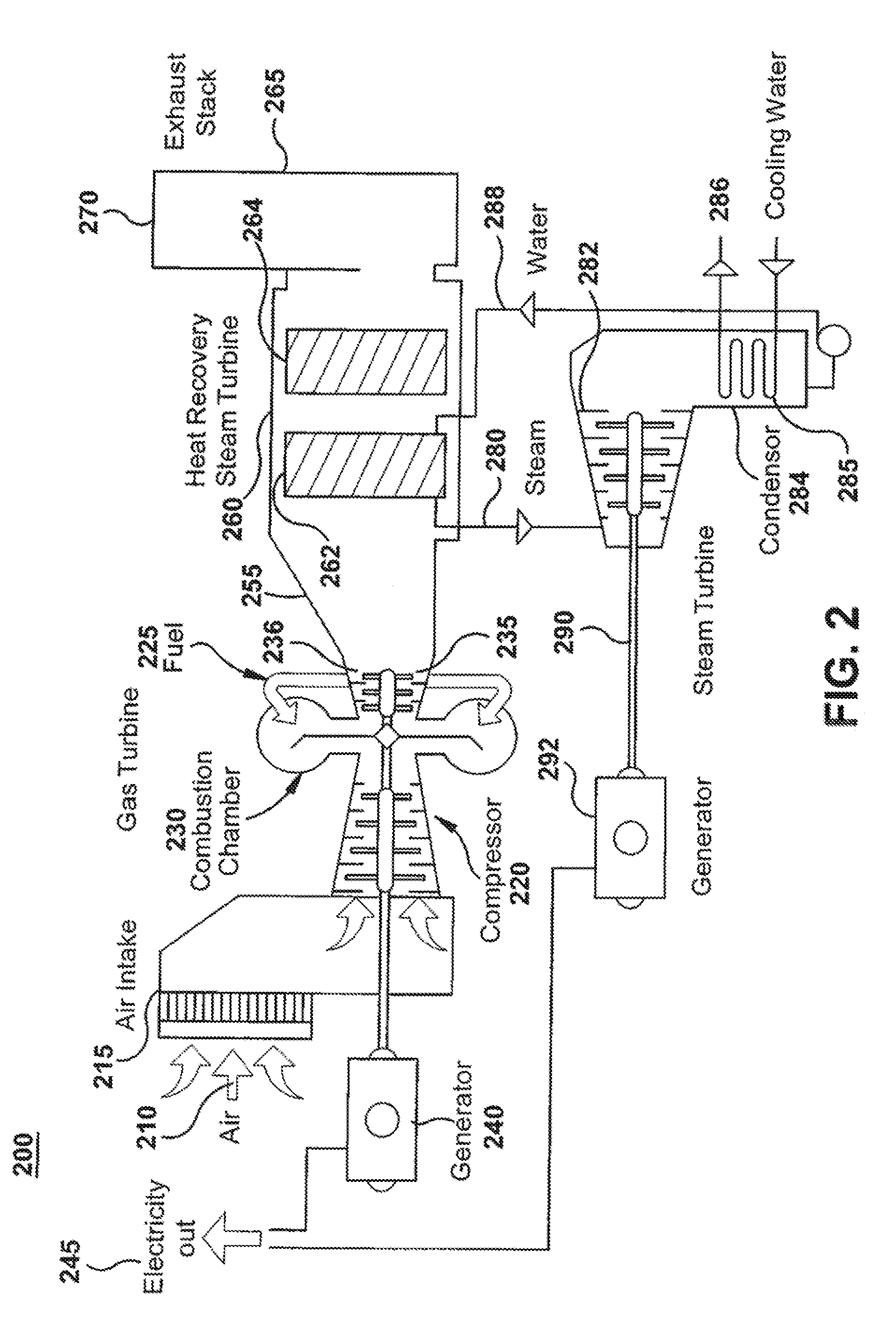
[0024]The following embodiments of the present invention have many advantages, including substantial reduction of the NO2 concentration in the exhaust stream over existing exhaust gas catalytic arrangements, leading to reduced NO2 emissions to the atmosphere. Such NO2 reductions may result in elimination of a “yellow plume” associated with elevated concentration of NO2 in atmospheric exhaust. The present invention may also lead to enhanced oxidation of volatile organic compounds (VOC) and unburned hydro carbons (UBC). Yet further, the present invention may result in reduced ammonia (NH3) consumption and reduced SCR catalyst surface area for removing NOx from the exhaust stream. The smaller required ammonia injection and SCR catalyst complex may result in a decreased pressure drop in the exhaust gas flow leading to greater output power from the gas turbine for a given fuel input.

[0025]FIG. 3 illustrates an internal arrangement of heat transfer equipment within an exemplary HRSG. HRSG...


PUM


Abstract

A power generating apparatus including a gas turbine engine combusting a fuel in air to produce shaft power and producing a flow of exhaust gases including oxides of nitrogen (NOx), carbon monoxide (CO) and hydrocarbons (HC). An emissions treatment apparatus includes in the exhaust gas flowpath a CO oxidation catalyst disposed at a location with an exhaust gas temperature for which the CO oxidation catalyst advantageously limits NO2 production. The emissions treatment apparatus further includes an ammonia injection apparatus, a mixing section, and a selective catalytic reduction element disposed downsteam of the ammonia injection apparatus and adapted for reduction of NOx.

Description

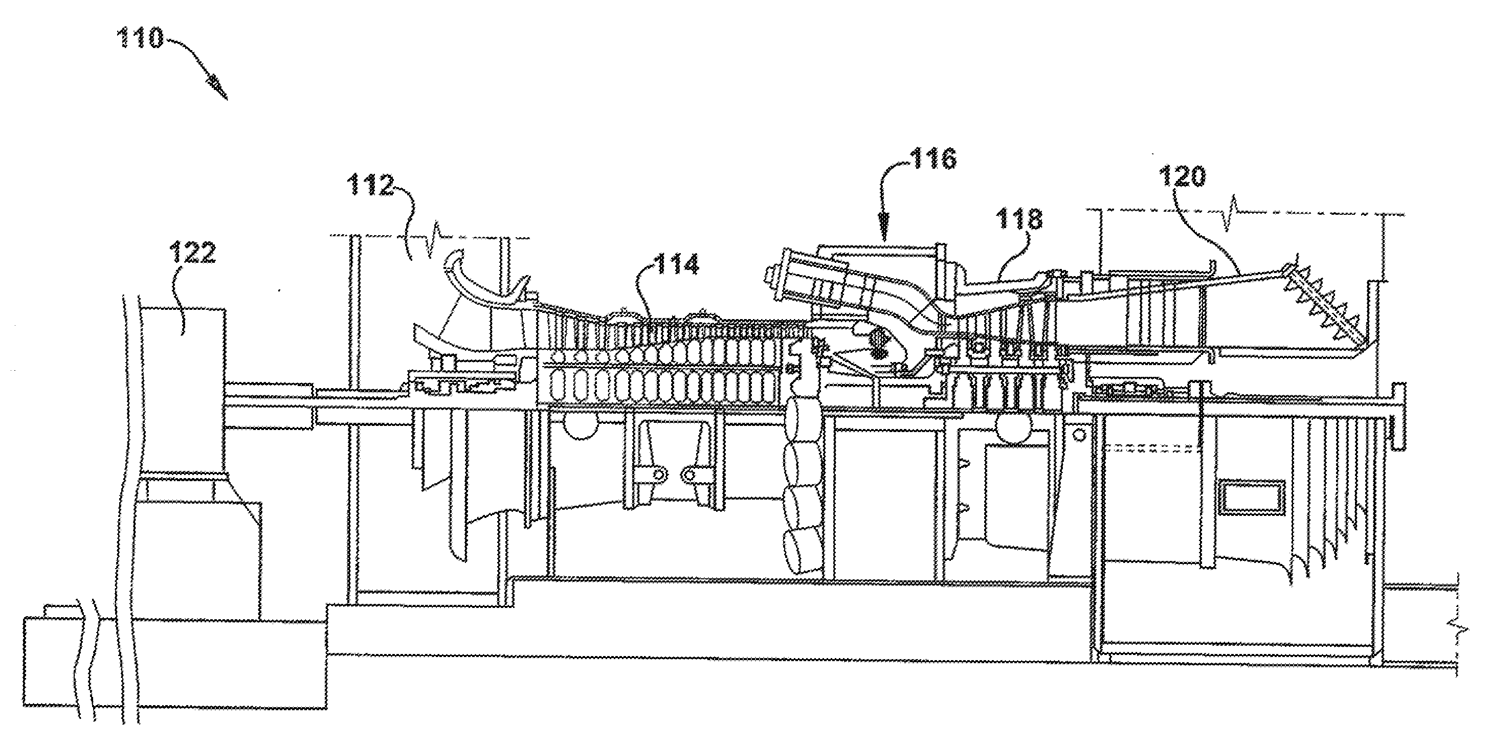
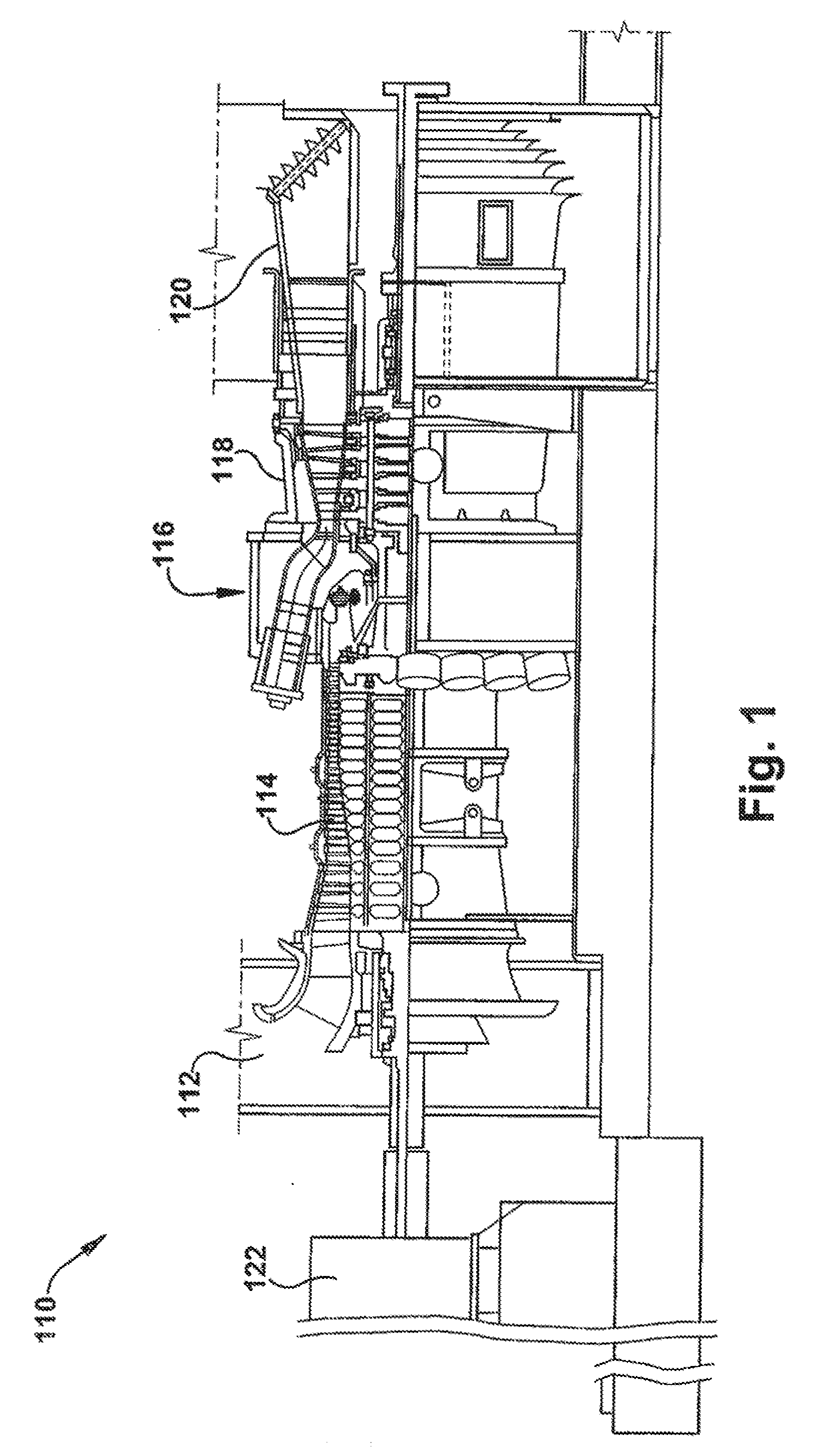
BACKGROUND OF THE INVENTION[0001]The invention relates generally to treatment of emissions in an exhaust path for a combustion system and more specifically to a method and apparatus for reducing NO2 formation in the exhaust path.[0002]FIG. 1 is a schematic illustration of an exemplary gas turbine system 10 including an intake section 112, a compressor section 114 coupled downstream from the intake section 112, a combustor section 116 coupled downstream from the intake section 112, a turbine section 118 coupled downstream from the combustor section 116, and an exhaust section 120. Turbine section 118 is rotatably coupled to compressor section 114 and to a load 122 such as, but not limited to, an electrical generator and a mechanical drive application.[0003]During operation, intake section 112 channels air towards compressor section 114. The compressor section 114 compresses inlet air to higher pressures and temperatures. The compressed air is discharged towards to combustor section 1...

Claims


Application Information

Patent Timeline
IPC IPC(8): B01D53/56F02C7/00C01B32/40
CPCB01D53/8656B01D53/90B01D2257/404Y02E20/16B01D2257/708F02C6/18B01D2257/502
Inventor KRAEMER, GILBERT O.
Owner GENERAL ELECTRIC CO
Learn More