
Wireless broadband communications network for a utility

Active Publication Date: 2010-08-26
ACLARA TECH LLC
View PDF46 Cites 4 Cited by
  • Summary
  • Abstract
  • Description
  • Claims
  • Application Information

AI Technical Summary

Benefits of technology

[0011]The network comprises a first tier that supports both wired and wireless nodes. The nodes include various sensors, instrumentation and remote monitoring devices installed at various sites including homes, factories, buildings and other facilities located throughout the utility's distribution area. A second tier of the system incorporates a plurality of data collection units (DCUs or substation points) to which information collected by the sensors, instrumentation and other devices is transmitted. A plurality of DCUs is employed in the system with each DCU collecting information from sites within a prescribed geographic area. Information from the respective sites is transmitted to the DCU at a first frequency. The DCUs within adjoining areas then transmit the information collected by the respective units to a central or regional site; e.g., a tower. This collected information is transmitted to the site at a second and higher frequency. Regardless of the transmission frequency used, adequate bandwidth is available for timely and reliable transmission of all data and other information.
[0012]The various sites within the system are meshed together to facilitate both data handling and ease of communication if, for example, a portion of the communications system is currently unusable or unreliable for some reason. It is a particular advantage of the system to rapidly handle significant amounts of information collected from throughout the area serviced by the utility, process that information so to provide a current overview of the utility's operations, and to quickly and reliably react to situations which arise at any location within the service or distribution area.

Problems solved by technology

Heretofore, it has been difficult for a utility to provide a service unique to each individual customer.
Further, utilities supplying electricity, water, or gas, experience periods of peak demands within different regions.
Third, is the level of individual users or consumption points.

Method used


Image

  • Wireless broadband communications network for a utility
  • Wireless broadband communications network for a utility
  • Wireless broadband communications network for a utility

Examples


Embodiment Construction

[0020]The following detailed description illustrates the invention by way of example and not by way of limitation. This description clearly enables one skilled in the art to make and use the invention, and describes several embodiments, adaptations, variations, alternatives and uses of the invention, including what is presently believed to be the best mode of carrying out the invention. Additionally, it is to be understood that the invention is not limited in its application to the details of construction and the arrangement of components set forth in the following description or illustrated in the drawings. The invention is capable of other embodiments and of being practiced or carried out in various ways. Also, it will be understood that the phraseology and terminology used herein is for the purpose of description and should not be regarded as limiting.

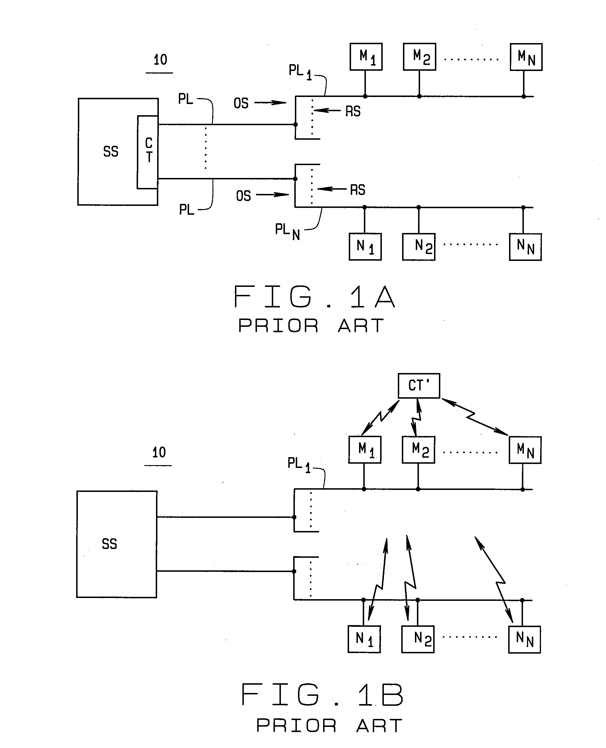
[0021]Referring to the drawings, FIG. 1A illustrates a communications system currently in use in which communications are sent to ...


PUM


Abstract

A communications network (12) for use by a utility (10) for communication, command, and control of the utility's distribution area for gas, water and electrical services including the utility's distribution system, security, workforce, and asset management. The network includes apparatus for obtaining information and data concerning usage of the electricity, gas, or water by each of the utility's customers, the operation of installations throughout the system, and how electricity, gas, or water is being distributed throughout the system. The information and data from each source (16) is processed to provide an up-to-date overview of the system and its operation to the utility's management and operating personnel. This includes identification of any current problems, including distribution or security, within the system, and asset monitoring and management to identify possible future problems which may occur within a predetermined period of time. Reports generated as a result of processing the information and data, besides providing current status information, also provide management and operating personnel with information as to ways of alleviating any current problems identified within the system, and steps which can be taken to forestall possible future problems which are identified.

Description

CROSS-REFERENCE TO RELATED APPLICATIONS[0001]U.S. provisional patent application 61 / 154,037 filed Feb. 20, 2009STATEMENT REGARDING FEDERALLY SPONSORED RESEARCH[0002]N / A.BACKGROUND OF THE INVENTION[0003]This invention relates to communications in the distribution system for a utility such as water, gas, or electrical utilities which may have numerous urban, suburban, and rural customers. More particularly, the invention relates to a multi-tiered communication system by which the utility can, among other things, quickly and reliably communicate with its customers, regardless of their location, so to ascertain information concerning the utility's operation throughout the system. This would include, for example, determining if there is an electrical outage within the system, or a gas line or water line break, the extent of any resulting problem, controlling and managing the utility's field workforce, monitoring the utility's assets where they are located (i.e., in situ), control of the ...

Claims


Application Information

Patent Timeline
IPC IPC(8): G08C17/02
CPCG01D4/004Y02B90/242Y04S20/42Y02B90/246Y04S20/322H04W24/04Y02B90/20Y04S20/30
Inventor SMITH, RONALDTHOMPSON, MARK
Owner ACLARA TECH LLC
Learn More