
Microfluidic system based on actuator elements

a microfluidic system and actuator technology, applied in the field of microfluidic systems, can solve the problems of long time required for good mixing, large passive structure, and inability to achieve good mixing,

Inactive Publication Date: 2010-08-26
STICHTING DUTCH POLYMER INST
View PDF2 Cites 24 Cited by
  • Summary
  • Abstract
  • Description
  • Claims
  • Application Information

AI Technical Summary

Benefits of technology

[0013]An advantage of the micro fluidic system according to embodiments of the present invention is that, because of the use of magnetic actuation, they may work with very complex, non-magnetic biological fluids such as e.g. saliva, sputum or full blood.
[0015]The microfluidic systems according to embodiments of the present invention are economical and simple to process, while also being robust and compact and suitable for complex fluids.
[0021]An advantage of the microfluidic device according to embodiments of the invention is that it provides enhanced actuation effects at equal or lower electrical currents with respect to prior art microfluidic systems in which magnetic actuation is obtained by a magnetic field generated by a current wire located in the wall of the microchannel at the first location.
[0036]The method according to the invention leads to a microfluidic system which shows enhanced actuation effects at equal or lower electrical currents with respect to prior art microfluidic systems in which magnetic actuation is obtained by a magnetic field generated by a current wire located in the wall of the microchannel at the first location.

Problems solved by technology

A challenge in microfluidic actuation is to design a compact and reliable microfluidic system for regulating or manipulating the flow of complex fluids of variable composition, e.g. saliva and full blood, in microchannels.
Nevertheless, passive structures need to be relatively large and a long time is needed for good mixing to occur.
Ultrasonic waves on the other hand are spatially not well confined.
Finally, both passive structures and ultrasonic waves do not provide effective mixing.

Method used


Image

  • Microfluidic system based on actuator elements
  • Microfluidic system based on actuator elements
  • Microfluidic system based on actuator elements

Examples


Embodiment Construction

[0066]The present invention will be described with respect to particular embodiments and with reference to certain drawings but the invention is not limited thereto but only by the claims. Any reference signs in the claims shall not be construed as limiting the scope. The drawings described are only schematic and are non-limiting. In the drawings, the size of some of the elements may be exaggerated and not drawn on scale for illustrative purposes.

[0067]Where the term “comprising” is used in the present description and claims, it does not exclude other elements or steps. Where an indefinite or definite article is used when referring to a singular noun e.g. “a” or “an”, “the”, this includes a plural of that noun unless something else is specifically stated.

[0068]Furthermore, the terms first, second and the like in the description and in the claims, are used for distinguishing between similar elements and not necessarily for describing a sequence, either temporally, spatially, in ranki...


PUM


Abstract

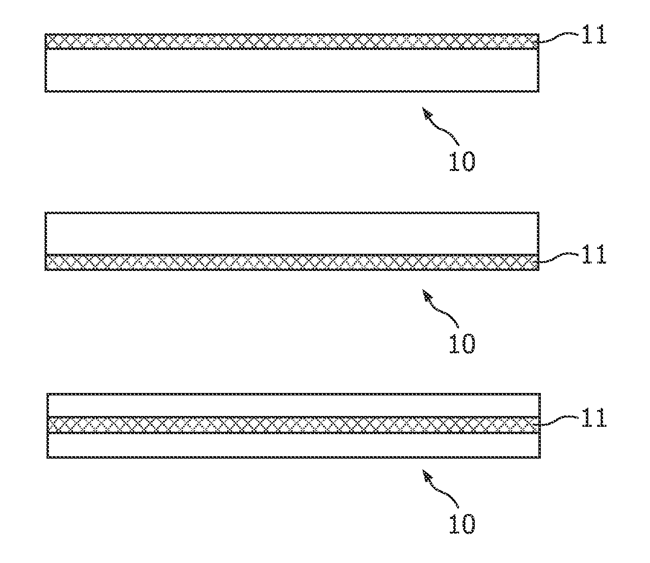
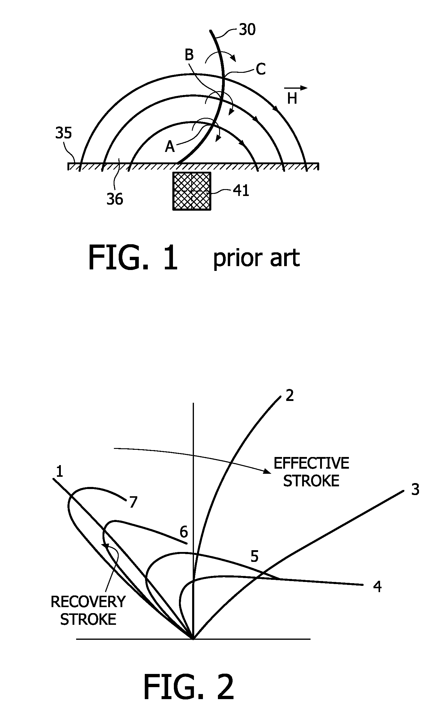
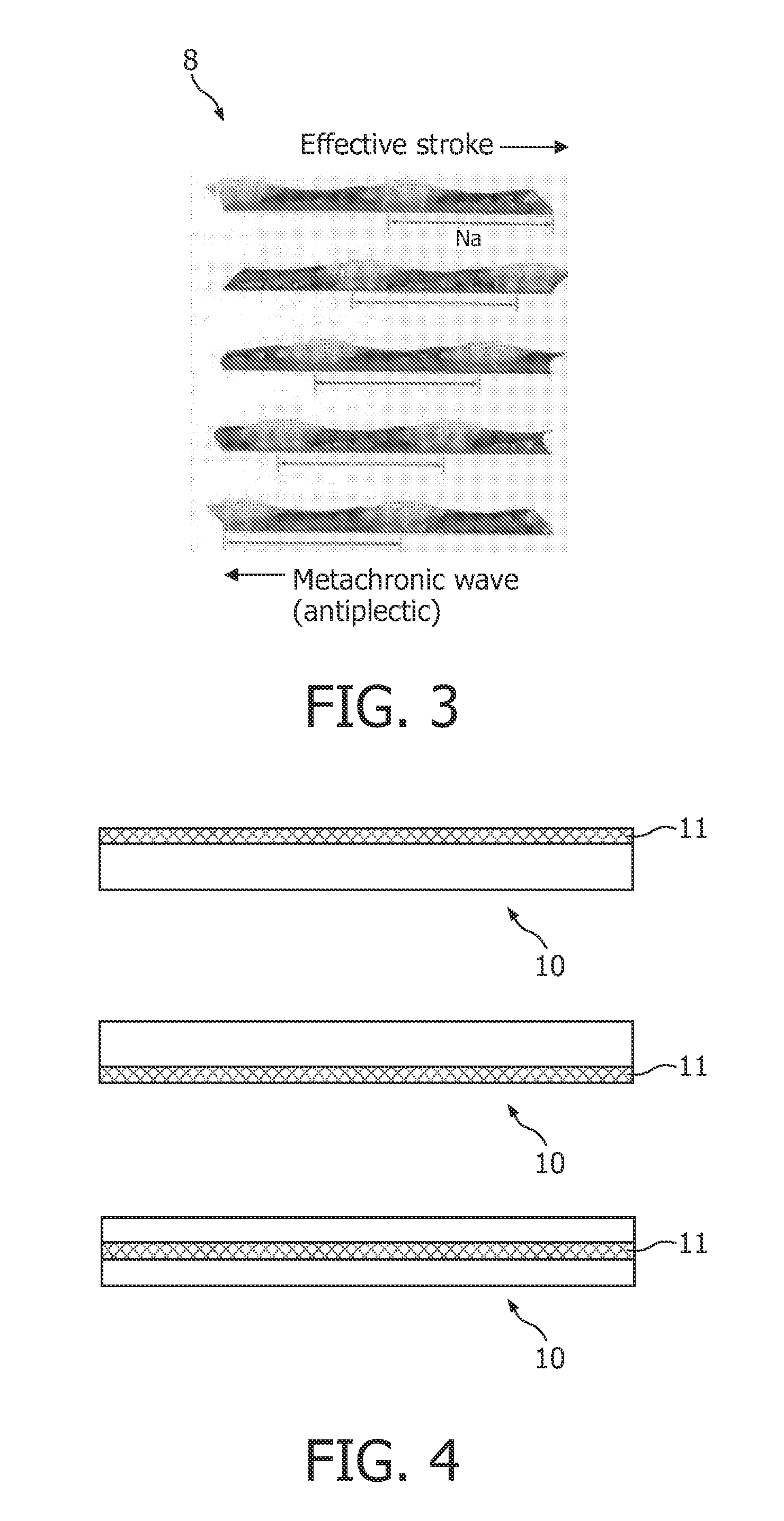
The present invention provides a microfluidic system comprising a plurality of ciliary actuator elements (10) located at an inner surface (14) of a wall (15) of a microchannel (16) of the microfluidic system at a first location. The microfluidic system furthermore comprises a magnetic field generator formed by at least one current wire (17) integrated in the wall (15) of the micro channel (16) at a second location substantially opposite to the first location with respect to a centre line of the microchannel (16). The present invention also provides a method for the manufacturing of such microfluidic systems and to a method for controlling a fluid flow through a microchannel (16) of such a microfluidic system.

Description

FIELD OF THE INVENTION[0001]The present invention relates to microfluidic systems, to a method for the manufacturing of microfluidic systems and / or to a method for controlling or manipulating a fluid flow through a microchannel of micro fluidic systems, as well as to a controller for controlling a fluid flow through a microchannel of a microfluidic system, and software for use with a microfluidic system in a method for controlling a fluid flow. The microfluidic systems may be used, for example, in biotechnological and pharmaceutical applications and in microchannel cooling systems in microelectronics applications. Microfluidic systems according to embodiments of the present invention can be compact, cheap and easy to process.BACKGROUND OF THE INVENTION[0002]Microfluidics relates to a multidisciplinary field comprising physics, chemistry, engineering and biotechnology that studies the behaviour of fluids at volumes thousands of times smaller than a common droplet. Microfluidic compon...

Claims


Application Information

Patent Timeline
IPC IPC(8): F15C1/00
CPCB01F13/0059B01F13/0091B01L3/502707B01L3/50273F04D33/00B01L2400/043B01L2400/0484F04B19/006B01L3/502746Y10T137/206B01F33/3038B01F33/30
Inventor DEN TOONDER, JACOB M. J.PRINS, MENNO W.J.FAHRNI, FRANCISVAN DZENDOORN, LEONARDUS J.
Owner STICHTING DUTCH POLYMER INST
Learn More