
Methods and devices for utilizing bondable materials

a technology of bondable materials and methods, applied in the direction of ligaments, shoulder joints, prostheses, etc., can solve the problems of loosening of bondable materials, time-consuming and potentially damaging to the tissue, and loosening of implants,

Active Publication Date: 2010-08-19
P TECH
View PDF101 Cites 113 Cited by
  • Summary
  • Abstract
  • Description
  • Claims
  • Application Information

AI Technical Summary

Benefits of technology

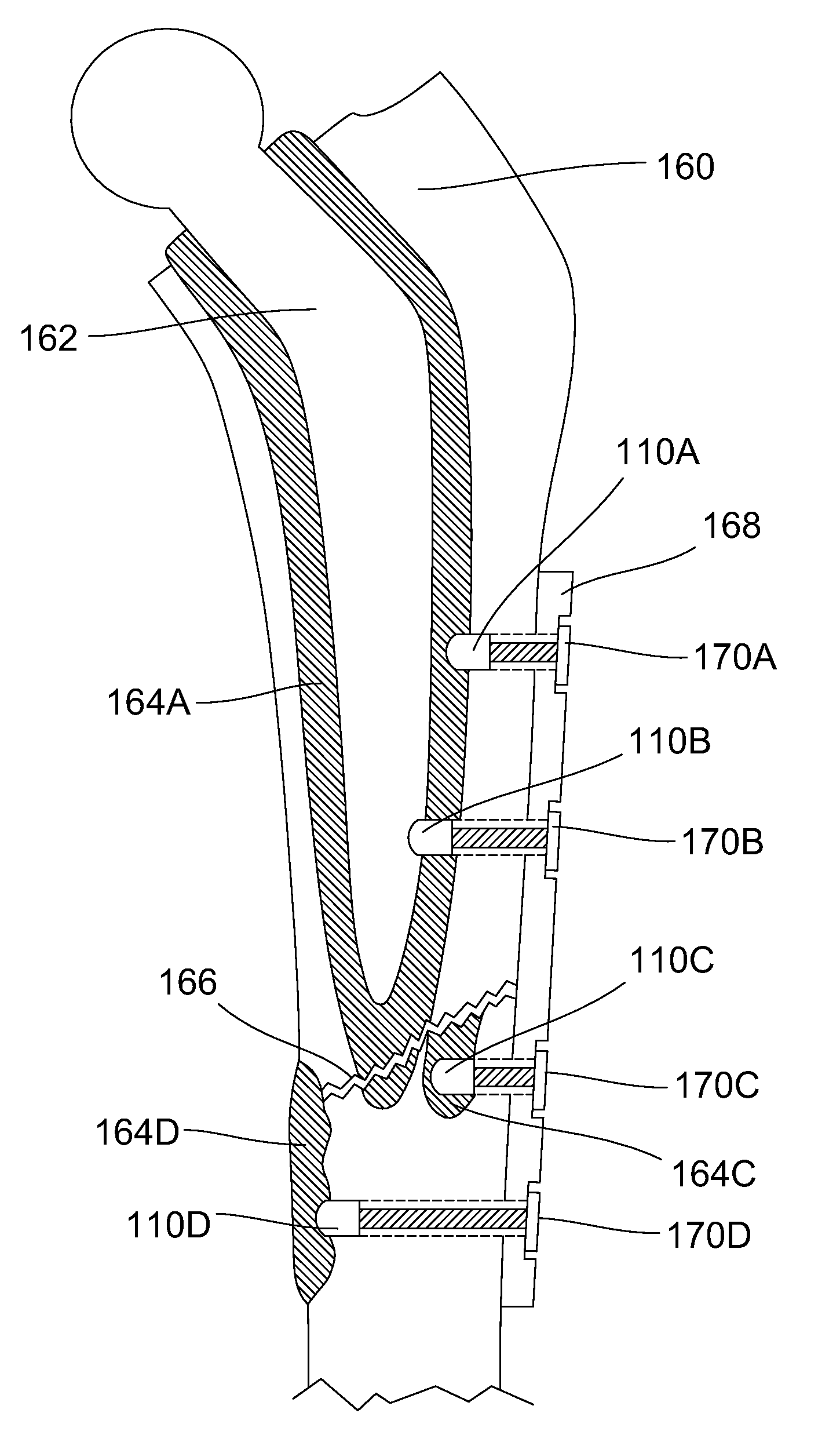
[0071]The fastener is adapted to be securely retained within the bondable material or adhesive, in one embodiment, by being provided with a shaped or contoured surface upon which the adhesive may grip once hardened. A roughened or porous surface may be provided alone or in combination with a shaped surface to increase purchase in bondable material and / or facilitate an interference fit.
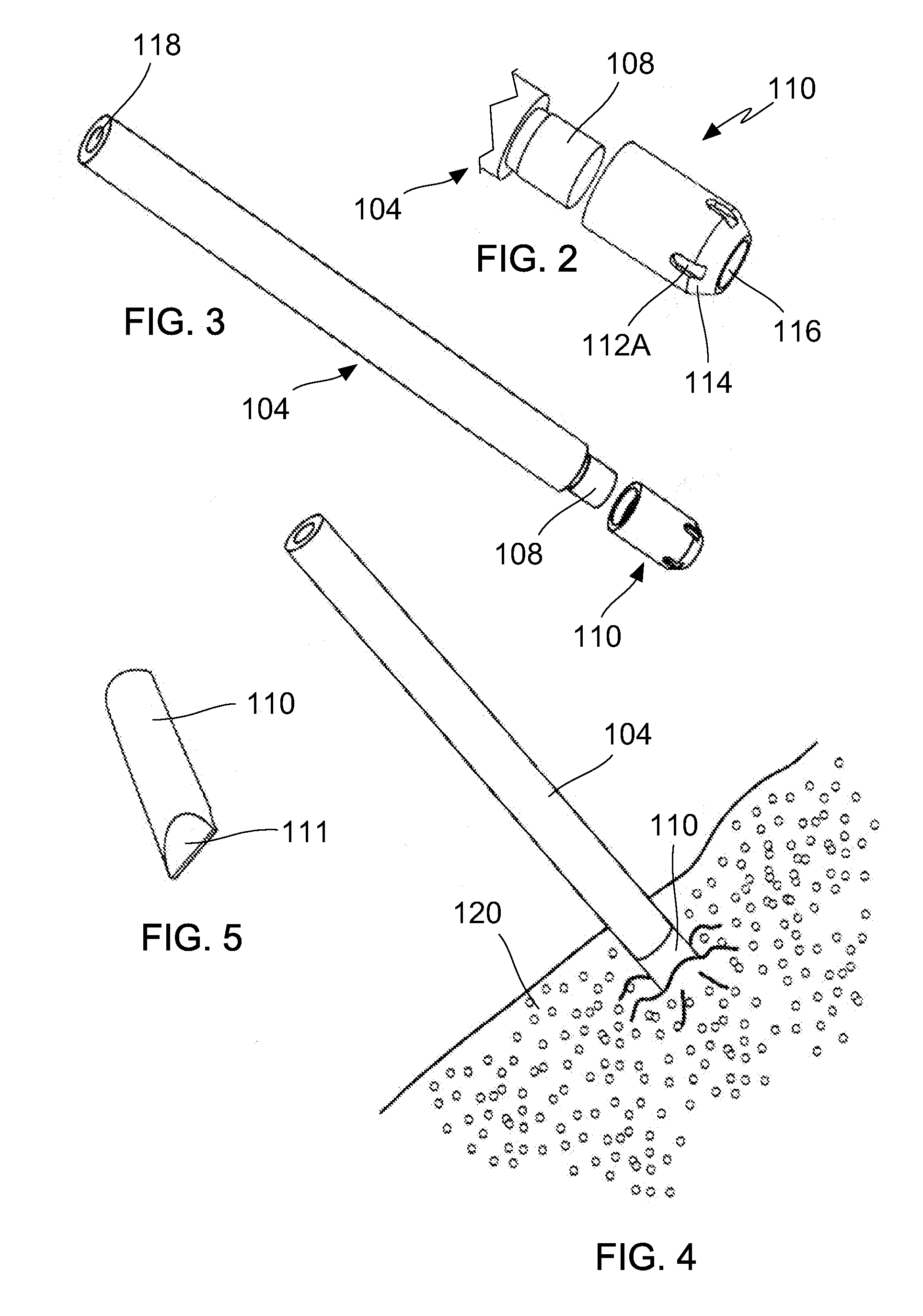
[0072]The fastener may further be provided with a taper at a leading end which first enters the adhesive. The taper improves performance, at least, by promoting accurate tracking and movement of the fastener into the adhesive, piercing tissue, and facilitating initial melting by concentrating vibratory energy over a smaller surface region.
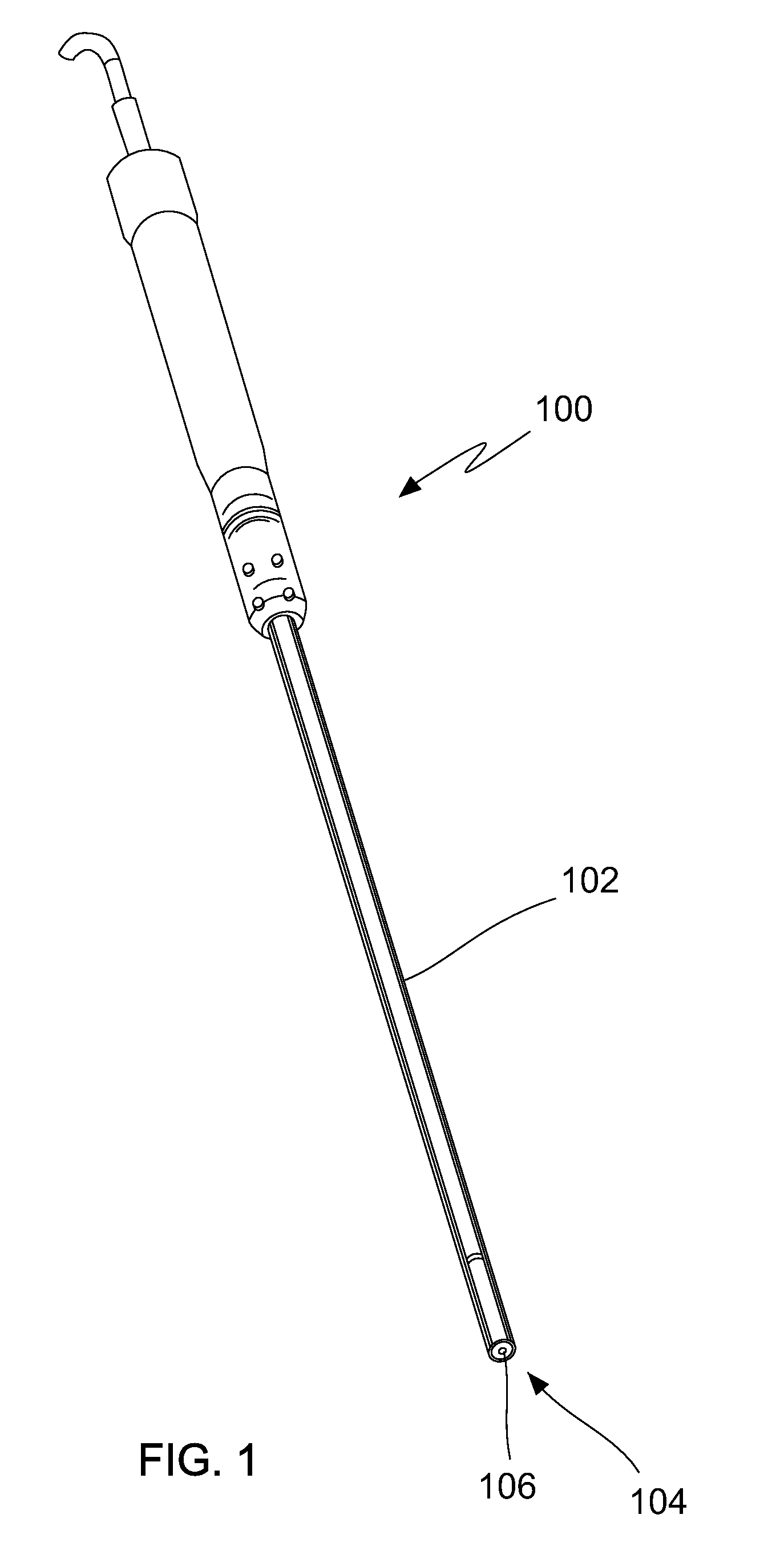
[0074]The embodiments of the present invention may be utilized with limitless fixation techniques and in conjunction with other fasteners and implants. Furthermore, the embodiments herein may assist in the installation and removal of tissue and implants. Moreover, the embodiments of the present invention may assist in the delivery of therapeutic agents and employ methods that facilitate tissue growth and repair. In addition, the embodiments herein may be used to apply vibratory energy to remove and / or install an implant in bondable material or to facilitate solidification and / or polymerization of the bondable material.

Problems solved by technology

Over time, these bondable materials may loosen due to tissue deterioration, improper installation of bondable materials, or deterioration of the bondable materials over time.
Conventional procedures require removal of the bondable material, which is time consuming and potentially damaging to the tissue.
Therefore, previous stabilization methods provided for the reapplication of bondable materials and did not utilize existing bondable materials.
However, some implants loose stability over time.
Again, this is a time consuming process, potentially damaging the surrounding tissue during the removal of the implant and remaining bondable material.
However, one drawback with plates and screws is that with the dynamic loading placed on the plate, loosening of the screws, and loss of stored compression can result.
One problem associated with the use of today's intramedullary rods is that it is often difficult to treat fractures at the end of the long bone.
However, the number and positioning of the bolt / screw openings are limited at the tip of the rod because of the decreased surface area of the rod and the reduced strength at the tip of the rod.
Fractured bone sections at the distal end of a femur, for example, may not be properly fastened to using conventional intramedullary rod stabilization techniques.
However, weak or fracture bones have limited purchase, as portions of the bone may be unfit for the use of bone screws.
Furthermore, if a intramedullary rod has been used to stabilize the bone, the fixation area is further limited as surgeons generally avoid tapping into areas of bone with an underlying intramedullary rod.
Existing systems and techniques for repairing tissue, like the ones previously described, can be complex, time consuming, lack the characteristic of being employed with precision, be damaging to tissue, and / or fail to provide a robust fastening of tissue.

Method used


Image

  • Methods and devices for utilizing bondable materials
  • Methods and devices for utilizing bondable materials
  • Methods and devices for utilizing bondable materials

Examples


Embodiment Construction

[0075]The invention relates to the devices and methods for the utilization of bondable materials and bondable materials, fixation and fastening of tissue to tissue, an implant to tissue, and an implant to an implant both inside and outside the body. The invention additionally relates to removing and anchoring implants to bondable materials and / or other biocompatible materials, anchoring implants using previously implanted and hardened bondable materials, and fixation using vibratory energy, mixing, solidifying, bonding, and / or mechanical interlocking of materials. The present invention also relates to the use of an energy source to install and / or remove an implant or bondable material or to facilitate the solidification and / or polymerization of a bondable material

[0076]The methods and devices disclosed herein may be used in conjunction with any medical procedure on the body. The stabilization, fastening, and / or repair of tissue or an implant may be performed in connection with any m...


PUM

PropertyMeasurementUnit
Energyaaaaaaaaaa

Abstract

The invention primarily relates to fastening and stabilizing tissues, implants, and / or bondable materials, such as the fastening of a tissue and / or implant to a bondable material, the fastening of an implant to tissue, and / or the fastening of an implant to another implant. This may involve using an energy source to bond and / or mechanically to stabilize a tissue, an implant, a bondable material, and / or other biocompatible material. The invention may also relate to the use of an energy source to remove and / or install an implant and / or bondable material or to facilitate solidification and / or polymerization of bondable material.

Description

CROSS REFERENCE TO RELATED APPLICATIONS[0001]This non-provisional application is based upon and herein claims priority to U.S. Provisional No. 61 / 155,133 filed Feb. 24, 2009. This application is related to U.S. patent application Ser. No. 12 / 202,210 filed Aug. 28, 2008, U.S. patent application Ser. No. 11 / 689,670 filed Mar. 22, 2007, U.S. patent application Ser. No. 11 / 671,556 filed Feb. 6, 2007, and U.S. patent application Ser. No. 11 / 416,618 filed May 3, 2006, the entire contents of each are hereby expressly incorporated by reference into this disclosure as if set forth fully herein.FIELD OF THE INVENTION[0002]The invention relates to the fastening and stabilizing of tissues, implants, and bondable materials, such as the fastening of a tissue and / or implant to a bondable material, the fastening of an implant to tissue, and / or the fastening of an implant to another implant. This may involve using an energy source to bond and / or mechanically stabilize a tissue, an implant, a bondabl...

Claims


Application Information

Patent Timeline
IPC IPC(8): A61B17/56
CPCA61B17/0401A61B17/11A61B17/1128A61B17/1146A61B17/320068A61B17/68A61B17/7059A61B17/7233A61B17/7266A61B17/866A61B17/8685A61B17/88A61B17/8836A61B17/8872A61B2017/005A61B2017/0409A61B2017/044A61B2017/1107A61F2/0811A61F2/30A61F2/30721A61F2/30756A61F2/3094A61F2/32A61F2/34A61F2/36A61F2/3603A61F2/38A61F2/3804A61F2/3859A61F2/389A61F2/40A61F2/4081A61F2/4202A61F2/44A61F2/4455A61F2/46A61F2/468A61F2002/067A61F2002/2817A61F2002/30062A61F2002/30065A61F2002/30067A61F2002/30133A61F2002/30451A61F2002/30576A61F2002/30604A61F2002/30677A61F2002/3068A61F2002/30785A61F2002/30787A61F2002/30878A61F2002/30892A61F2002/30894A61F2002/30971A61F2002/30973A61F2002/3401A61F2002/3403A61F2002/444A61F2002/4619A61F2002/4683A61F2210/0004A61F2210/0071A61F2220/0058A61F2230/0015A61F2250/0068A61F2310/00011A61F2310/00365A61F2310/00383A61F2310/00952A61L24/001A61L24/046C08L33/04A61B2017/32007
Inventor BONUTTI, PETER M.CREMENS, MATTHEW J.BEYERS, JUSTIN E.
Owner P TECH
Learn More