Lamp system and lighting apparatus

Inactive Publication Date: 2010-08-19
TOSHIBA LIGHTING & TECH CORP +1
View PDF28 Cites 46 Cited by
  • Summary
  • Abstract
  • Description
  • Claims
  • Application Information

AI Technical Summary

Benefits of technology

[0007]Thus, it becomes possible to radiate the heat generated by the LED into air by heat conduction from the substrate to the metallic cover and at the same time to efficiently radiate the heat from the transparent cover into air because heat is efficiently conducted to the transparent cover having a large surface area exposed to the outside through the metallic heat conduction part and the resin heat conduction part. Thus, radiation performance of the lamp system can be improved and it becomes possible to respond to high power output by the LED. Moreover, since the transparent cover is made of resin, it becomes possible to easily form the resin heat conduction part to be a shape having higher thermal conductivity with the metallic heat conduction part, compared to a case of a glass cover. Therefore, it becomes possible to ensure high thermal conductivity.
[0009]The metallic cover includes, for example, a metal having good thermal conductivity such as aluminum and may be formed to have a cylindrical or discoidal shape. The other surface side of the substrate may be brought into thermal surface contact with the one surface side of the metallic cover. On a peripheral surface part of the metallic cover, a plurality of fins may be formed or a vent hole which penetrates inside and outside of the metallic cover may be formed to improve radiation performance. The metallic heat conduction part may have any of the structures such as a groove portion, protrusion, or a screw structure as long as the resin heat conduction part can be fitted with the metallic heat conduction part.
[0011]A heat conduction filler for improving radiation performance may be mixed into the transparent cover. If a filler having high light diffusion property is used, light diffusion property of the transparent cover can be improved.
[0013]Thus, it becomes possible to improve thermal conductivity from the metallic heat conduction part to the resin heat conduction part to further improve radiation performance.
[0016]Thus, it becomes possible to place a finger on the finger portion to easily manipulate attachment and detachment of the lamp system to and from a socket device of the lighting apparatus.
[0019]Thus, it becomes possible to provide a lighting apparatus having a lamp system which has a long lifetime.

Problems solved by technology

Especially, in a case where an LED having a larger amount of heat generation than a discharge lamp is used as the light source, if radiation of heat is not sufficiently carried out, temperature of the LED itself becomes high to cause deterioration of the LED and shorter lifetime of the LED.
However, if the fluorescent lamp is simply replaced by an LED, sufficient radiation performance cannot be obtained and therefore a problem arises that the lamp cannot respond to high power output by the LED.

Method used


Image

  • Lamp system and lighting apparatus
  • Lamp system and lighting apparatus
  • Lamp system and lighting apparatus

Examples


first embodiment

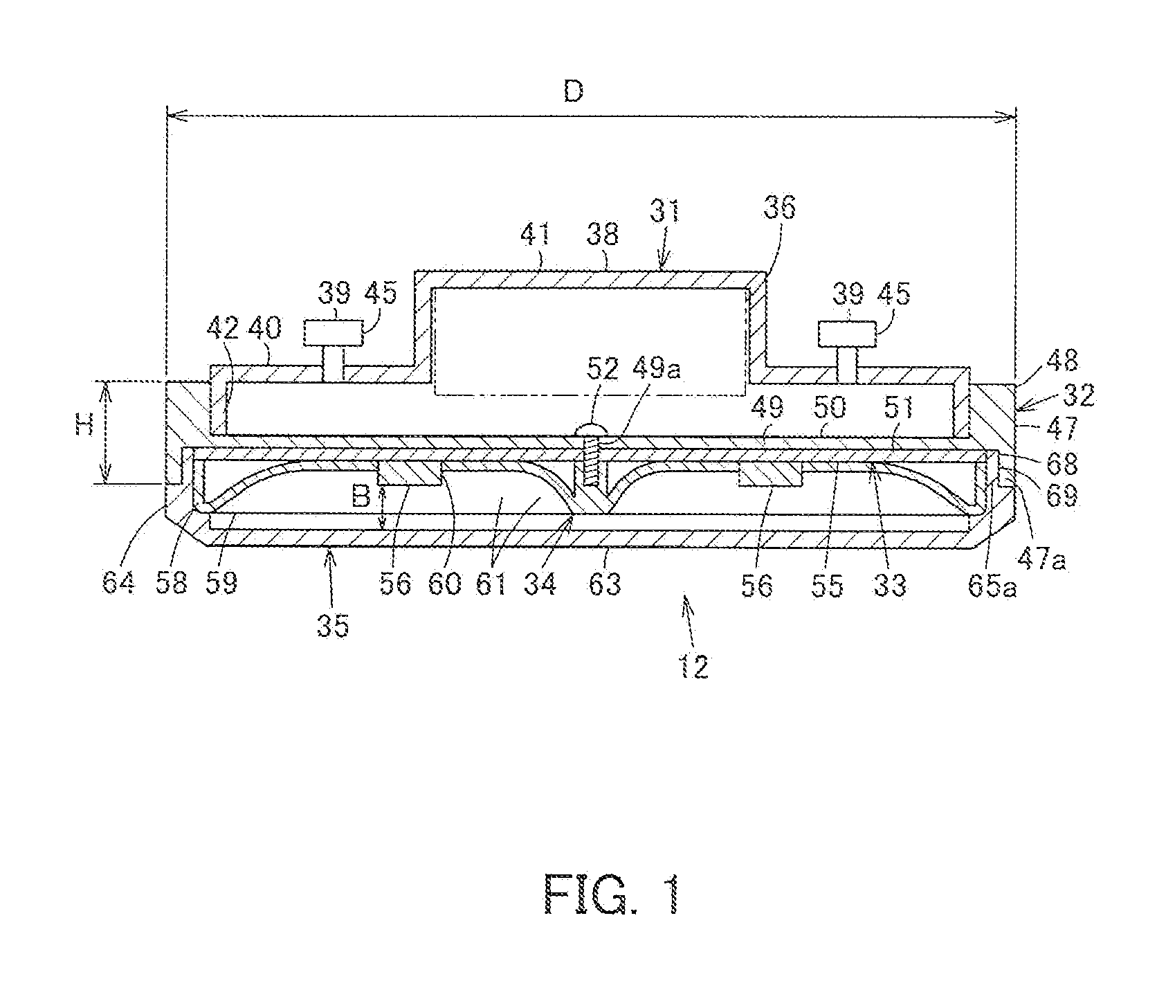
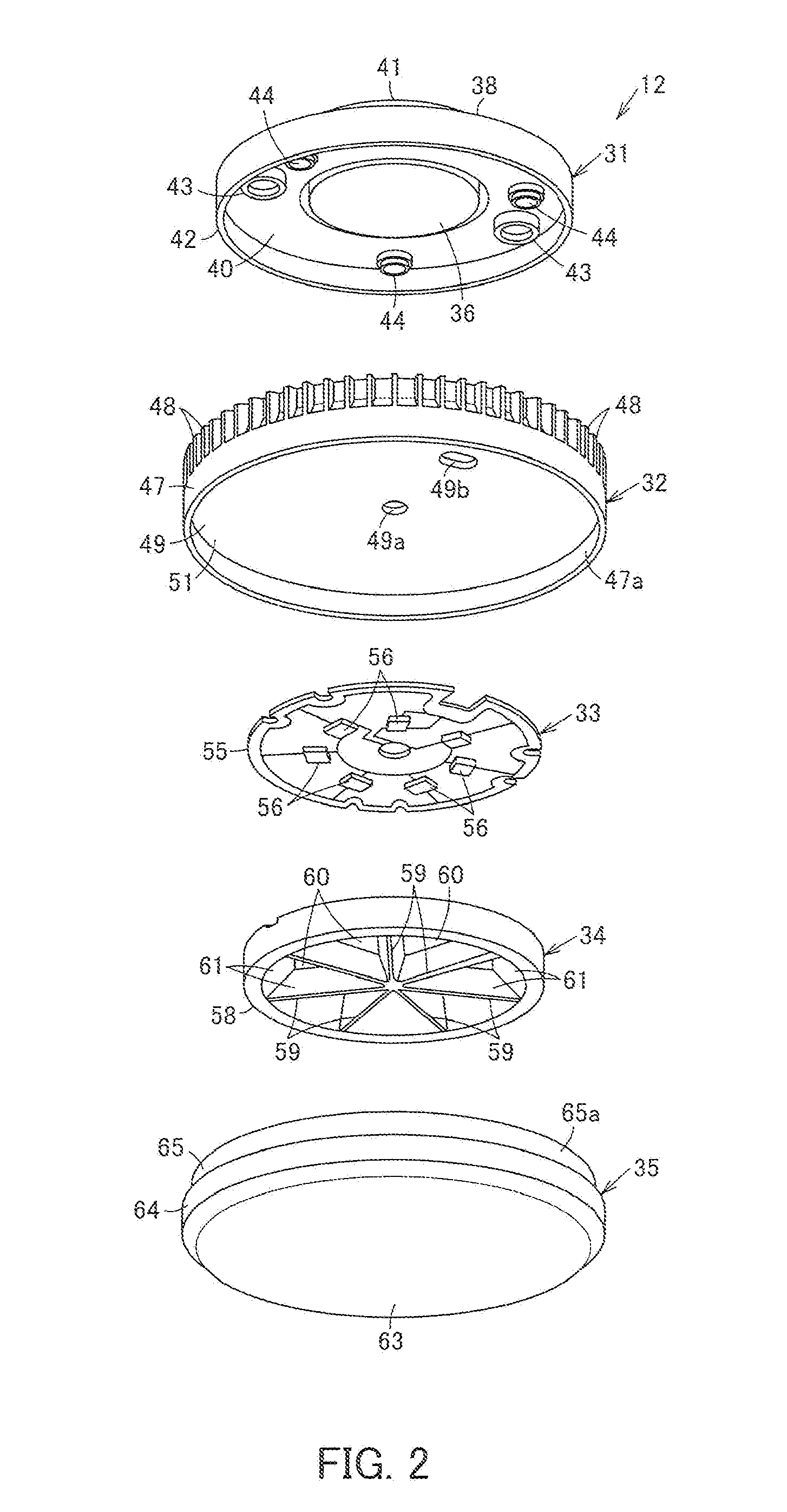
[0033]A first embodiment is shown in FIGS. 1 to 5.

[0034]As shown in FIG. 5, the lighting apparatus is, for example, a downlight and includes an apparatus main body 10, a socket device 11 attached to the apparatus main body 10, and a flat lamp system 12 mounted to the socket device 11. Here, regarding the direction such as the vertical direction, the following explanation will be made on the assumption that a light source side which is one surface side of the lamp system 12 is a lower side and a cap side which is the other surface side is an upper side in a condition where the flat lamp system 12 is horizontally set.

[0035]The apparatus main body 10 is made of a metal or a resin and has a flat board part 15, a reflection board part 16, and an edge part 17 for attachment onto the ceiling. A lower surface of the apparatus main body 10 is opened. In this apparatus main body 10, the socket device 11 is provided on a lower surface of the flat board part 15 so that the lamp system 12 can be...

second embodiment

[0081]Next, a second embodiment is shown in FIG. 6. FIG. 6 is a partial cross-sectional view of the metallic cover 32 and the transparent cover 35 of the lamp system 12.

[0082]A circular groove part 78, which is open to the lower surface side of the external circumference part 47, functions as the metallic heat conduction part 47a of the metallic cover 32 and a circular projection 79 which perpendicularly protrudes from an upper edge surface of the side surface part 64 to be fitted with the groove part 78 functions as the resin heat conduction part 65a of the transparent cover 35.

[0083]The groove part 78 and the projection 79 are fitted to bring the metallic cover 32 and the transparent cover 35 into contact so as to enable heat conduction. In the case of this structure, the contact area between the groove part 78 and the projection 79 can be large and therefore thermal conductivity can be increased. Moreover, by making the heat conductive material 69 intervene between the groove par...

third embodiment

[0085]Next, a third embodiment is shown in FIG. 7. FIG. 7 is a cross-sectional view in which a part of the reflector 34 and a part of the transparent cover 35 of the lamp system 12 are enlarged.

[0086]An example in which the front surface and side surface of the reflector 34 and the transparent cover 35 are not in contact is shown. In this example, the light introduction part 73 of the transparent cover 35 becomes the inner surface of the front surface part 63 and the side surface part 64 facing the space 72. In this example also, similar to the first embodiment, the light of the LED 56 can be introduced from the light introduction part 73 and guided to the side surface part 64.


PUM


Abstract

A lamp system which can improve radiation performance is provided. A metallic heat conduction part provided along a peripheral portion of a metallic cover is fitted with a resin heat conduction part provided along a peripheral portion of a transparent cover so as to thermally contact each other. Heat generated by an LED is radiated into air from the metallic cover and at the same time is efficiently conducted from the metallic cover to the transparent cover to be radiated into air from the transparent cover.

Description

FIELD OF THE INVENTION[0001]The present invention relates to a lamp system using an LED as a light source and a lighting apparatus using the lamp system.BACKGROUND OF THE INVENTION[0002]Conventionally, there is a lamp system using a GX53 type cap as described in Japanese Laid-Open Patent Publication No. 2008-140606. This lamp system has a flat shape which is vertically thin and includes a metallic cover. The GX53 type cap is provided on an upper surface side of the metallic cover and a flat fluorescent lamp is provided on a lower surface side of the metallic cover as a light source together with a transparent cover which covers the fluorescent lamp. On an upper surface of the cap, a pair of lamp pins to be connected to a socket are provided in a protruding manner while a lighting device for making the fluorescent lamp light by receiving power supplied through the lamp pins is stored inside the cap. Then, heat generated by lighting of the fluorescent lamp is radiated to the outside f...

Claims


Application Information

Patent Timeline
IPC IPC(8): F21V29/00
CPCF21K9/00F21V29/89F21V3/04F21V7/0016F21V7/0091F21V15/01F21V17/12F21V21/03F21V29/004F21Y2101/02F21K9/30F21V3/02F21V19/0005F21V29/773F21V29/83F21S8/04F21K9/20F21Y2115/10F21V29/71
Inventor SAKAI, MAKOTOSHIMIZU, KEIICHITANAKA, TOSHIYAOSAWA, SHIGERUHISAYASU, TAKESHIOGAWA, KOZOSUWA, TAKUMIKAWANO, HIOTSHI
Owner TOSHIBA LIGHTING & TECH CORP
Why Eureka
Try Eureka