
Image Generation System

Inactive Publication Date: 2010-08-19
WOODARD WILLIAM BRYAN
View PDF6 Cites 61 Cited by
  • Summary
  • Abstract
  • Description
  • Claims
  • Application Information

AI Technical Summary

Benefits of technology

[0085]In a further embodiment the processor is programmed to vary at least one image parameter the first image to improve image clarity (e.g. by increasing brightness) when the eye-tracking system detects the user looking at a said part of the first image. Thus, by looking at various parts of an ‘unclear’ first image the user may make clear those parts.
[0094]In another embodiment the processor may determine a parameter of a part of the image to be displayed on the first display from the output signals from the eye-tracking system indicative of a level of saccade. For example, in one embodiment, the brightness of the image generated on the first display may increase if the eye-tracking system detects a predetermined level of rapid saccadic eye-movements.
[0105]The present invention may thus provide an improved image generation system, capable of generating an image on a screen based on eye-movement and bio-feedback of a user.
[0124]The present invention may thus provide an improved sound generation system, capable of generating a sound from a speaker based on eye-movement and bio-feedback of a user.
[0155]The present invention may thus provide an image generation system capable of generating an image indicative of a user's eye-fixation and physiological response when viewing an image.

Problems solved by technology

Users whose hands (or other limbs) are occupied, constrained, restrained, paralyzed or disabled are clearly impeded from maneuvering a pen or interface device without assistance and are thus hampered from controlling a computer, or drawing an image.
The DuRousseau system however does not track where the user is looking.
While the Smyth system provides an effective system for controlling machines or the like, Smyth does not describe any way in which the system could be used for generation or control of images.

Method used


Image

  • Image Generation System
  • Image Generation System
  • Image Generation System

Examples


Embodiment Construction

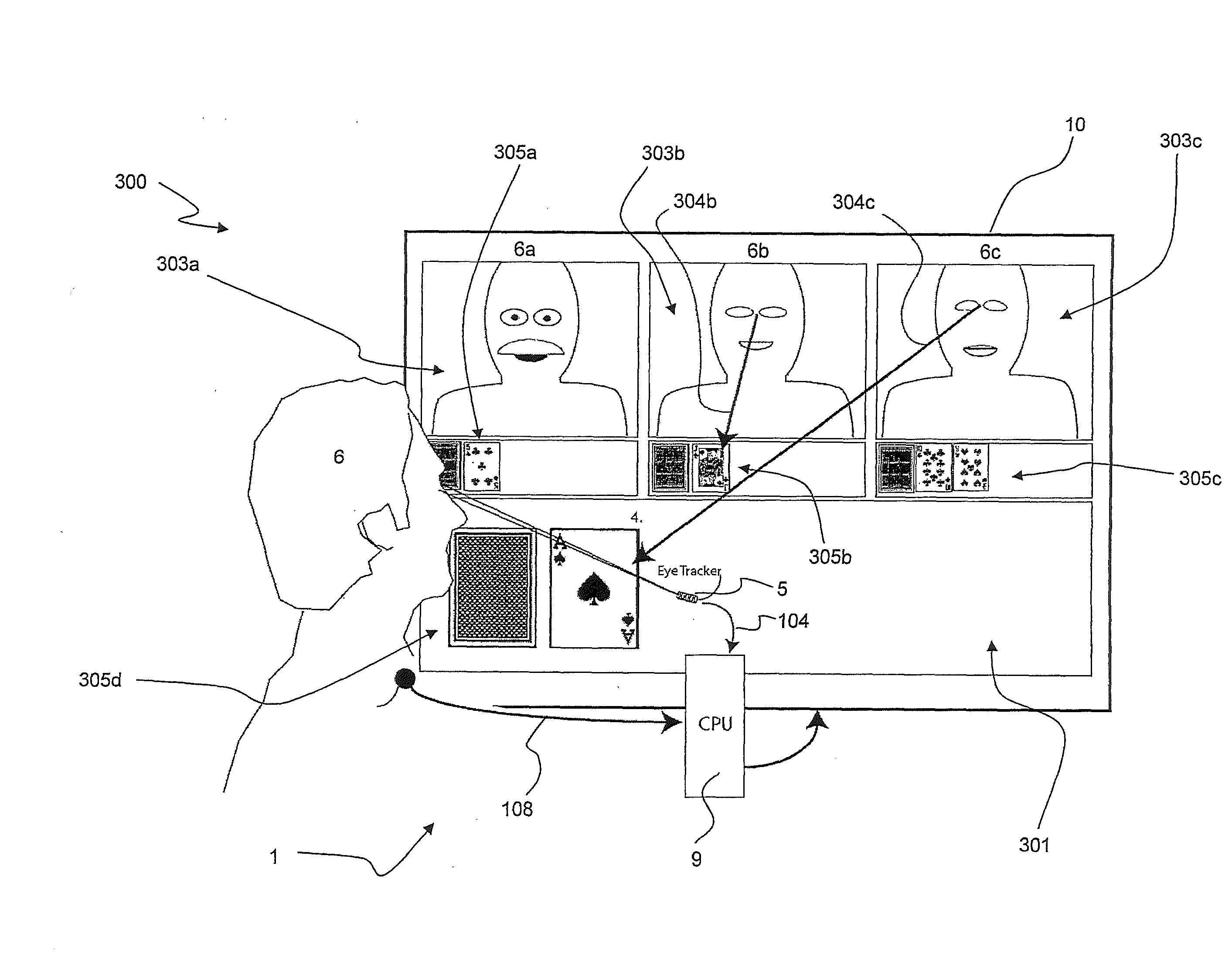
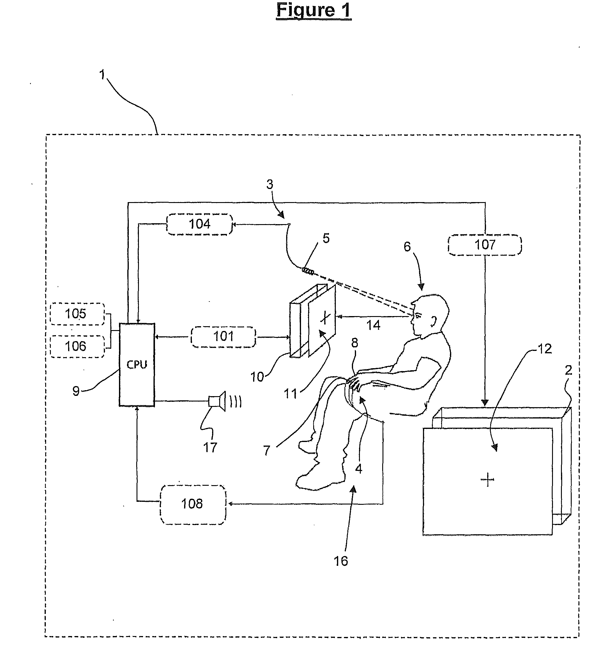
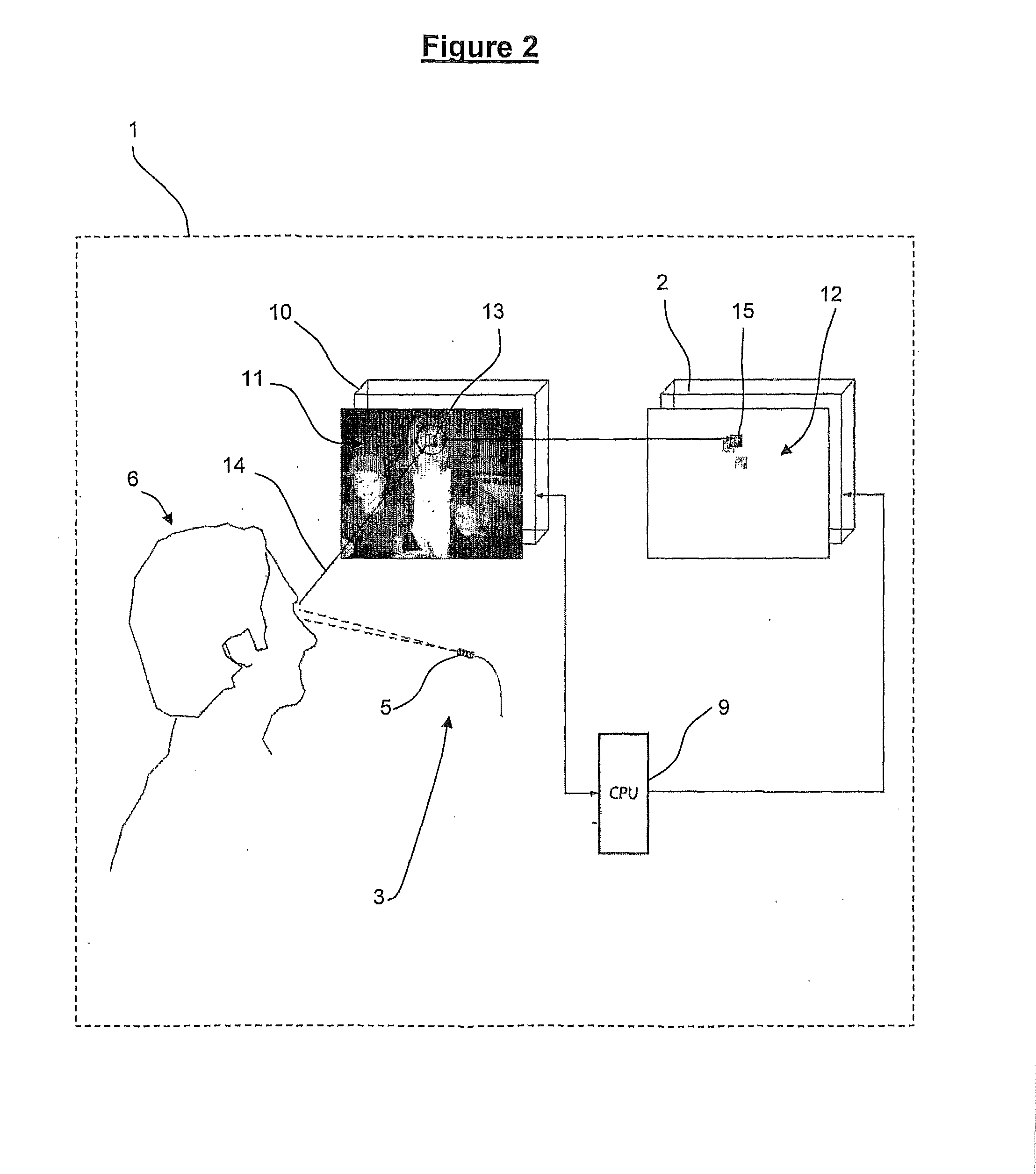
[0166]FIG. 1 shows an image generation system (1) according to one preferred embodiment of the present invention. The image generation system (1) has a ‘first’ display screen (2) for displaying an image (12) indicative of the signals from an eye-tracking system (3) and bio-feedback sensors (4).

[0167]The eye-tracking system (3) has an oculometer (5) capable of determining the eye-orientation of a user (6) and outputting a signal indicative of same. The oculometer (5) thus allows the viewing direction or ‘eye-fixation’ (14) of the user (6) to be determined.

[0168]The bio-feedback sensors (4) are provided as sensory pads (7) attached to the fingers (8) of the user (6) and form part of a bio-feedback system (16). The sensory pads (7) are capable of outputting a signal dependant on the heart-rate, galvanic skin response or other physiological function of the user (6).

[0169]The image generation system (1) has a digital signal processor (9) programmed to receive and process the output signa...


PUM


Abstract

An image generation system for generating an image on a display screen. The image generation system includes an eye-tracking system capable of determining a user's eye orientation and outputting a signal indicative of same. The image generation system also includes a bio-feedback sensor capable of detecting activity of one or more physiological functions of the user and outputting a signal indicative of the level of activity. A processor is included and is adapted to receive and process the output signals from the eye-tracking system and bio-feedback sensor. The processor determines an image to be generated on the display screen indicative of the signals from the eye-tracking system and bio-feedback sensor.

Description

CROSS-REFERENCE TO RELATED APPLICATIONS[0001]This application is a continuation of PCT application number PCT / NZ2008 / 000212, filed Aug. 15, 2008, the entire contents of which are incorporated herein by reference, which claims the benefit of New Zealand patent application serial number 560457 filed Aug. 15, 2007 and New Zealand patent application serial number 560457 filed Jul. 14, 2008.TECHNICAL FIELD[0002]The present invention relates to an image generation system.[0003]In particular, the present invention relates to an image generation system and method using bio-feedback and eye-tracking systems.BACKGROUND ART[0004]The generation of pictures, text and other images is an important component in human communication. Images provide a permanent or semi-permanent mode of communication capable of relaying a great amount of information in a small timeframe.[0005]Images are also one of the fundamental expressions of human creativity and may be used to convey emotions, thoughts, informatio...

Claims


Application Information

Patent Timeline
IPC IPC(8): G09G5/00H04N7/18
CPCG06F3/013G09G5/00
Inventor WOODARD, WILLIAM BRYAN
Owner WOODARD WILLIAM BRYAN
Learn More