
Electromagnetic Induction Handwriting System and Coordinate Determining Method Thereof

a technology of electromagnetic induction and handwriting, applied in the field of handwriting system, can solve problems such as waste of time and cos

Active Publication Date: 2010-08-19
WACOM CO LTD
View PDF6 Cites 97 Cited by
  • Summary
  • Abstract
  • Description
  • Claims
  • Application Information

AI Technical Summary

Benefits of technology

[0015]Therefore, it would be advantageous to provide an electromagnetic induction handwriting system and its coordinate determining method that can overcome the defects of the prior art.
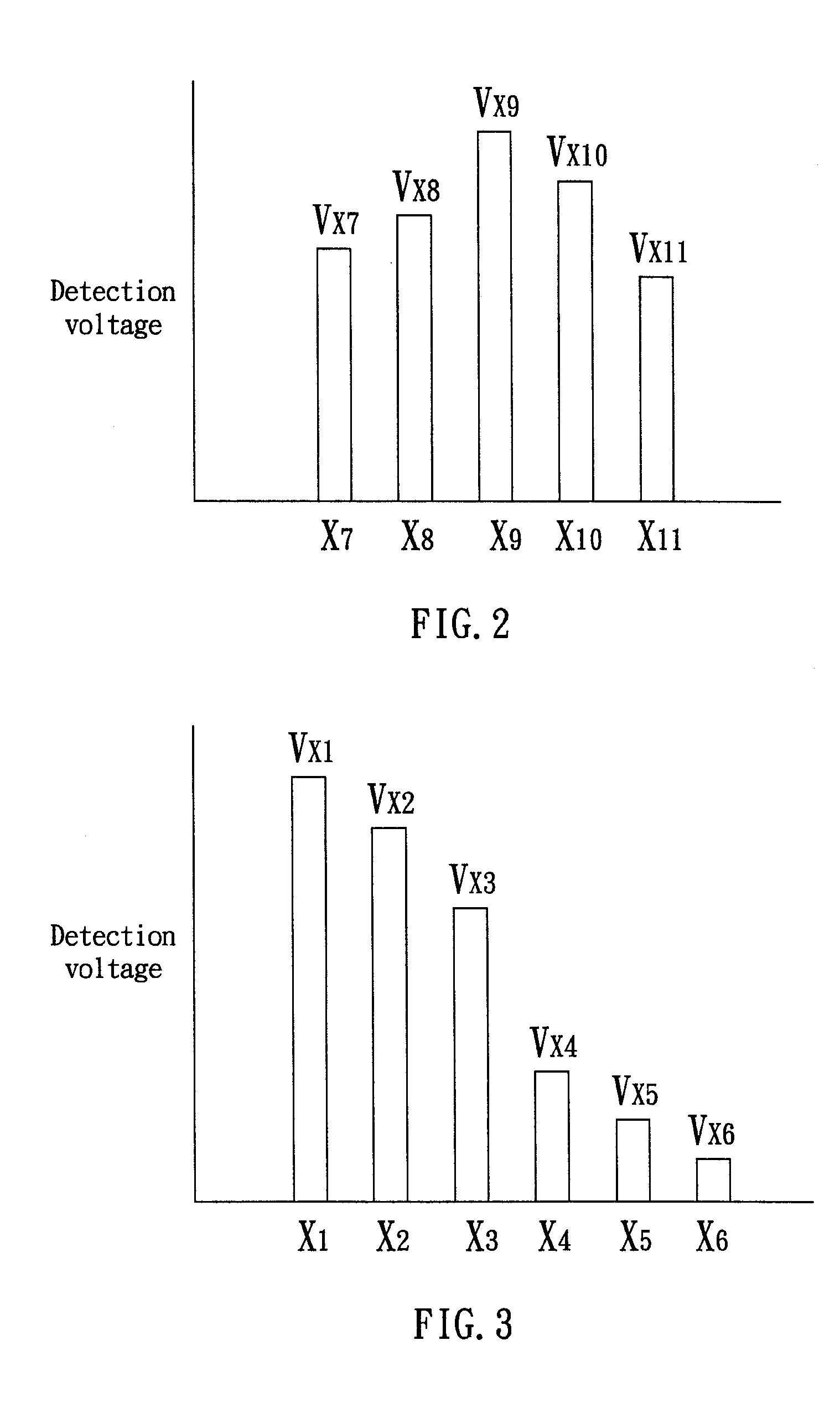
[0018]According to the object, the present invention provides a coordinate determining method for determining a coordinate of a stylus on a handwriting device. The comprises: providing a x-y loop antenna array; proceeding with a sequence of comparison procedure to compare the detection voltages of the x-y loop antenna array with a noise-judge value, such that a first voltage, a second voltage, and a third voltage are obtained, wherein the first voltage equals the maximum detection voltage, the second voltage and the third voltage are obtained from two antennas, and both of the two antennas are arranged at the same side of the antenna that induces the maximum detection voltage; and computing the coordinate of the stylus according to the first voltage, the second voltage, and the third voltage.
[0021]The detailed description of the present invention will be discussed in the following embodiments, which are not intended to limit the scope of the present invention, but can be adapted for other applications. While drawings are illustrated in details, it is appreciated that the quantity of the disclosed components may be greater or less than that disclosed, except expressly restricting the amount of the components. Wherever possible, the same or similar reference numbers are used in drawings and the description to refer to the same or like parts.

Problems solved by technology

However, the value of error of the computed position corresponding to f(θ) are obtained from experiential value; this will waste time and cost.
Nakamura et al. determines the coordinate by a linear equation in two variables that will inevitably result in inaccuracy.

Method used


Image

  • Electromagnetic Induction Handwriting System and Coordinate Determining Method Thereof
  • Electromagnetic Induction Handwriting System and Coordinate Determining Method Thereof
  • Electromagnetic Induction Handwriting System and Coordinate Determining Method Thereof

Examples


Embodiment Construction

[0021]The detailed description of the present invention will be discussed in the following embodiments, which are not intended to limit the scope of the present invention, but can be adapted for other applications. While drawings are illustrated in details, it is appreciated that the quantity of the disclosed components may be greater or less than that disclosed, except expressly restricting the amount of the components. Wherever possible, the same or similar reference numbers are used in drawings and the description to refer to the same or like parts.

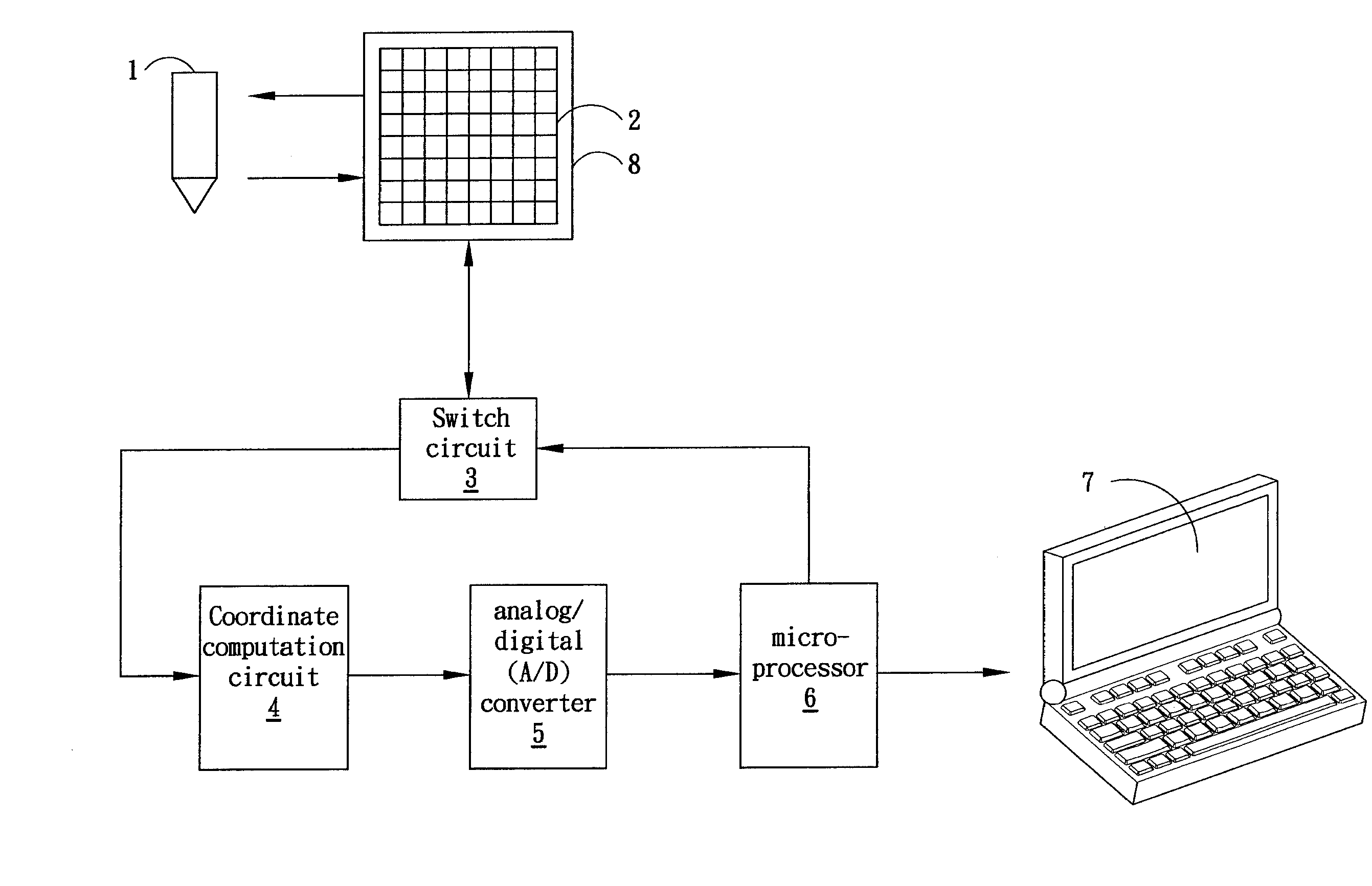
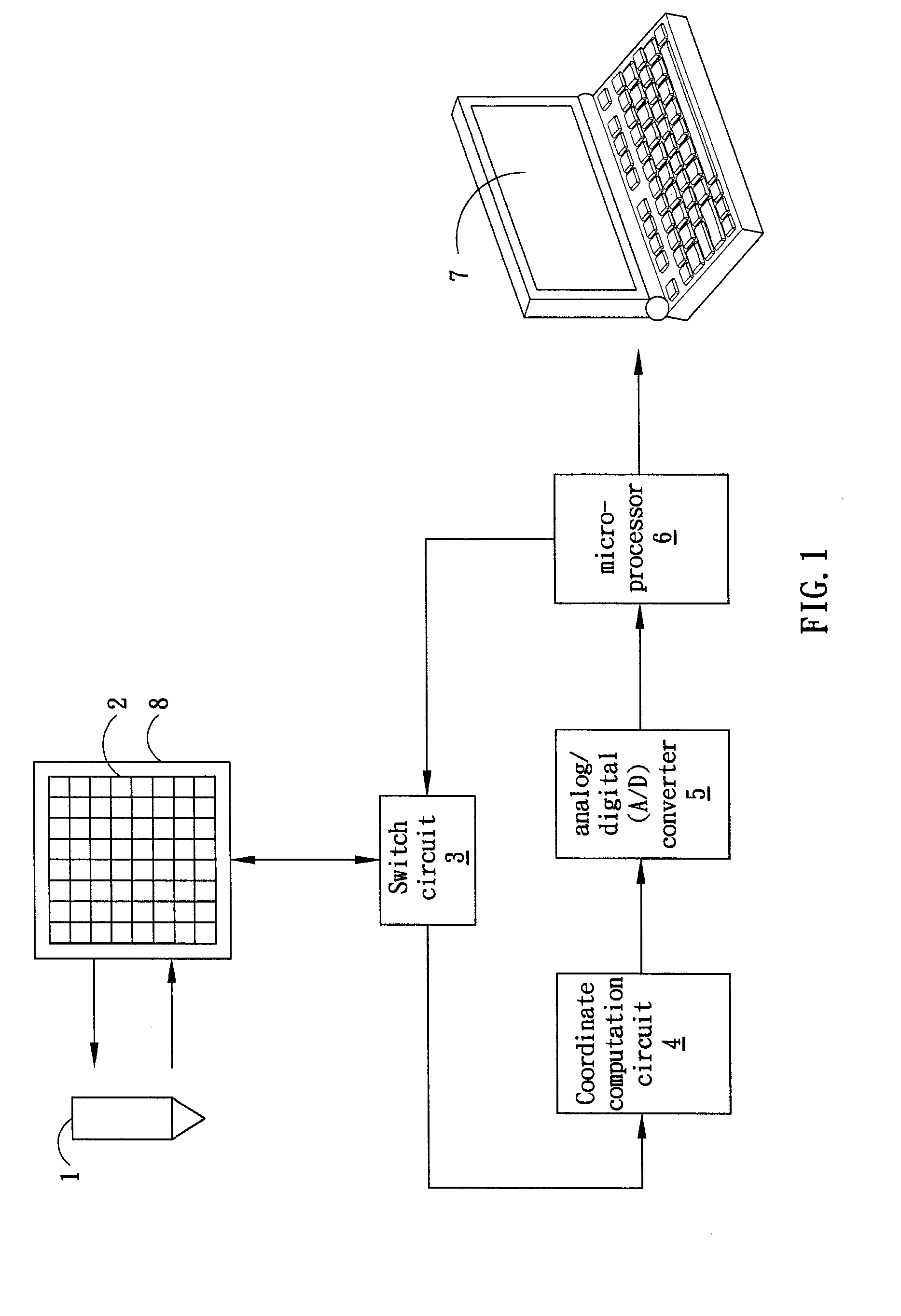
[0022]FIG. 1 shows an electromagnetic induction handwriting system according to one embodiment of the present invention. The electromagnetic induction handwriting system comprises a stylus 1, an x-y loop antenna array 2 arranged inside of a handwriting device 8, a switch circuit 3, a coordinate computation circuit 4, an analog / digital (A / D) converter 5, a microprocessor 6, and a computer 7. By switching the switch circuit 3, the microp...


PUM


Abstract

The present invention discloses an electromagnetic induction handwriting system and its single side coordinate determining method for determining a coordinate of a stylus on a handwriting apparatus. The coordinate is computed by a first voltage, a second voltage, and a third voltage, where the first voltage equals the maximum detection voltage, the second voltage and the third voltage are obtained from two antennas, and both of the two antennas are arranged at the same side of the antenna that induces the maximum detection voltage.

Description

BACKGROUND OF THE INVENTION[0001]1. Field of the Invention[0002]The present invention relates to a handwriting system, and more particularly, to a handwriting system having single side coordinate determining method.[0003]2. Description of the Prior Art[0004]A handwriting system, for example, a tablet, a digitizer, a white board, and so forth, includes two major kinds of inputting method: electromagnetic induction type and touch panel type.[0005]For example, a tablet comprises an inputting surface and an independent stylus. When the stylus presses or approaches the inputting surface, electrical field is caused by electromagnetic induction, and the coordinate of the stylus is detected. For sensing the electric field, the tablet may comprise an x-y loop antenna array, multiplexers, band pass filter, rectifier, integrator, peak detector, A / D converter, frequency counter, and microprocessor.[0006]Many apparatus and their coordinate detecting methods for detecting the coordinate of the st...

Claims


Application Information

Patent Timeline
Patent Type & Authority Applications(United States)
IPC IPC(8): G08C21/00
CPCG06F3/03545
Inventor YEH, CHIA-JUI
Owner WACOM CO LTD
Learn More