Distributor power line communication system

Inactive Publication Date: 2010-08-12
EANDIS
View PDF7 Cites 21 Cited by
  • Summary
  • Abstract
  • Description
  • Claims
  • Application Information

AI Technical Summary

Benefits of technology

[0003]It is an aim of the present invention to provide a more reliable distributor power line communication system.
[0011]The use of these filters can considerably reduce the recurring operating and maintenance cost for the network operator normally required to keep the PLC system running and can hence offer a large cost benefit. Furthermore, the signal to noise ratio can be improved a lot, so that far less retransmissions are required and the use of more efficient modulations like QPSK and QAM can be considered. These can offer a larger bandwidth efficiency (=data speed divided by bandwidth used) than FSK or other bandwidth inefficient modulation schemes which are commonly used for PLC so that functions that require more capacity and lower latency become feasible.
[0012]In preferred embodiments, each power line communication filter is a passive filter circuit comprising a first electric component having a first predetermined impedance for blocking the predetermined frequency band used for power line communication and a second electric component having a second impedance for passing a second frequency band encompassing the mains frequency of the power distribution network. An example of such a passive filter circuit comprises one or more parallel resonant circuits, for example LC-networks, which is inserted between the power distribution network and the end user installation, having impedances in such a way that a rejection frequency band covering the used frequency range of the PLC modems is obtained. Preferably the center of the rejection frequency band is at least two decades higher than the mains frequency to limit the impact of the filters on the transmission of electrical power on the mains frequency.
[0016]In preferred embodiments, the smart metering devices may be further provided with a communication interface towards end user appliances, such as for example a local area network interface, a wireless interface (e.g. Bluetooth), a home power line communication interface or other. In this way, for example, the power distributor can achieve control over home appliances such as for example electric boilers, heating devices, washing machines, dryers and the like, or other appliances, and switch them on / off according to a given timing scheme. This can result in an overall more flat power consumption, which is beneficial from the viewpoint of electric power production, transport and distribution. The interface can also be used to connect other consumption metering devices, such as for example water and gas consumption metering devices, enabling remote read-out of these as well.

Problems solved by technology

From experiences all over the world results show that PLC communication is rather unreliable and in many cases is interrupted for several hours a day because a lot of noise and distortion is generated by all kinds of appliances in houses and buildings.
Furthermore, the HF-power injected by the PLC modems on the outside cables or lines is severely limited by the very low and varying impedances seen on the LV-connections to the customers and in the LV-substation on the power transformer.

Method used


Image

  • Distributor power line communication system
  • Distributor power line communication system
  • Distributor power line communication system

Examples


Embodiment Construction

[0025]The present invention will be described with respect to particular embodiments and with reference to certain drawings but the invention is not limited thereto but only by the claims. The drawings described are only schematic and are non-limiting. In the drawings, the size of some of the elements may be exaggerated and not drawn on scale for illustrative purposes. The dimensions and the relative dimensions do not necessarily correspond to actual reductions to practice of the invention.

[0026]Furthermore, the terms first, second, third and the like in the description and in the claims, are used for distinguishing between similar elements and not necessarily for describing a sequential or chronological order. The terms are interchangeable under appropriate circumstances and the embodiments of the invention can operate in other sequences than described or illustrated herein.

[0027]Moreover, the terms top, bottom, over, under and the like in the description and the claims are used fo...


PUM


Abstract

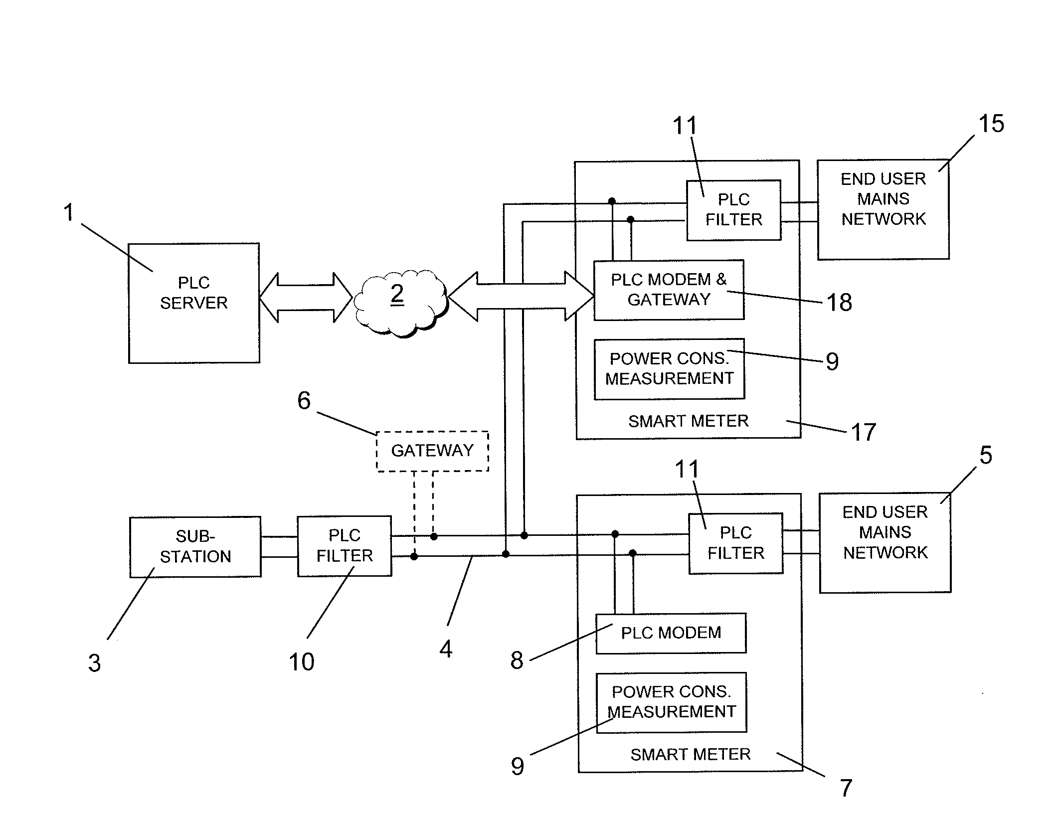
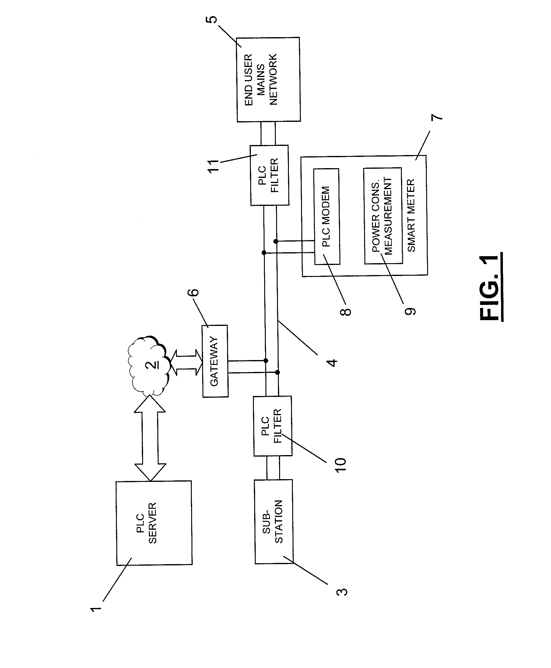
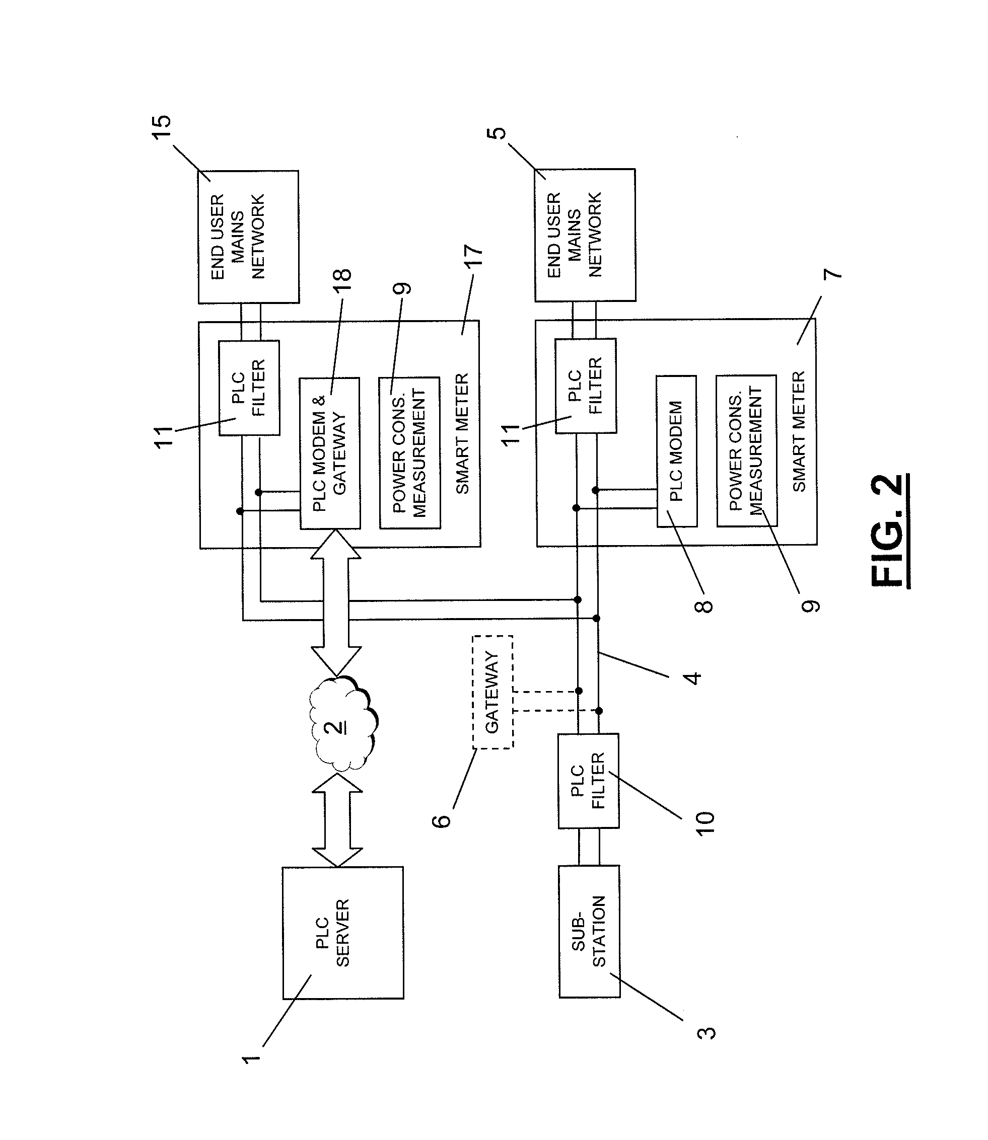
Distributor power line communication system comprising a communication server (1) sending and receiving messages over a telecommunication network (2), a power distribution substation (3) to which a power distribution network (4) towards end users (5) is connected, at least one gateway (6; 18) transferring messages from the telecommunication network (2) onto the power distribution network (4) in a predetermined frequency band, a plurality of smart metering devices (7; 17; 27) at end user mains networks for measuring power consumption and comprising a power line communication modem (8; 18) sending and receiving messages within the predetermined frequency band over the power distribution network (4), power line communication filters (10, 11) on power lines connecting the power distribution network and the end user mains networks and on power lines connecting the power distribution network to the power distribution substation, each filter blocking frequencies within the predetermined frequency band.

Description

TECHNICAL FIELD[0001]The present invention relates to the field of power line communication (PLC).BACKGROUND ART[0002]In the coming years, utility companies, in casu those that operate distribution networks for electricity, will start replacing most or all of their electromechanical Ferraris meters by so called “smart meters” that can be read remotely. Several ways to communicate with those meters exist, but one in particular is ideally suited for the task, namely Power Line Communication or PLC. It offers two major advantages: it is in the hands of the LV network operators themselves and it is a means to get “plug and play” operation as the meter is automatically connected to the communication platform as the meter is branched to the low voltage network. From experiences all over the world results show that PLC communication is rather unreliable and in many cases is interrupted for several hours a day because a lot of noise and distortion is generated by all kinds of appliances in ...

Claims


Application Information

Patent Timeline
IPC IPC(8): G06F1/26
CPCH04B3/542H04B2203/5491H04B2203/5433H04B3/56
Inventor HENDERIECKX, LUC
Owner EANDIS
Why Eureka
Try Eureka