
System and method for measuring light scattering in the eyeball or eye region by recording and processing retinal images

a technology of retinal image and light scattering, which is applied in the field of visual optics, ophthalmology and optometry, can solve the problems of difficult and cumbersome application in clinical practice, no widely accepted robust method for objective measurement, and low impact on visual quality after correction. , to achieve the effect of facilitating measurement and facilitating patient comfor

Active Publication Date: 2010-08-05
UNIV POLITECNICA DE CATALUNYA
View PDF4 Cites 16 Cited by
  • Summary
  • Abstract
  • Description
  • Claims
  • Application Information

AI Technical Summary

Benefits of technology

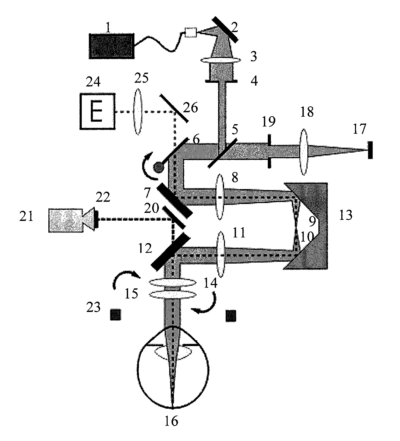
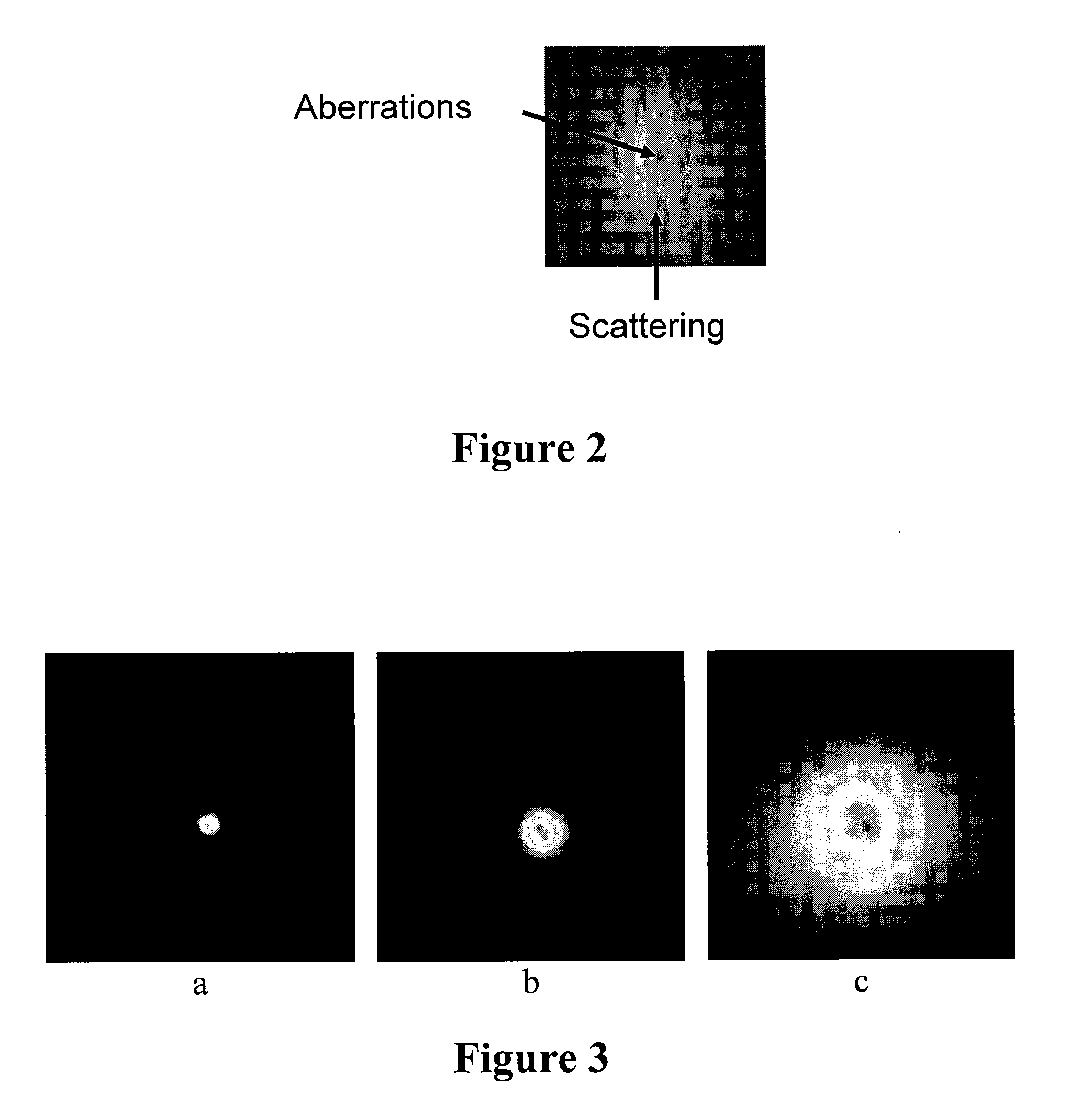
[0042]As previously described, the method herein described is based on retrieving information on intraocular scattering which is located in the outermost part of double-pass images. For one embodiment, a particular object of the invention is the objective quantification of intraocular scattering by determining the objective scattering index (OSI). This index can be calculated using the ratio between the energy present in the outer part of the image and the central part thereof or, moving to the frequency domain, determining the area under the curve of the modulation transfer function, once the contribution of the low frequencies which do not provide information about intraocular scattering has been eliminated. The method described is robust, completely objective and the OSI can be used to classify patients with cataracts and select them for surgery.
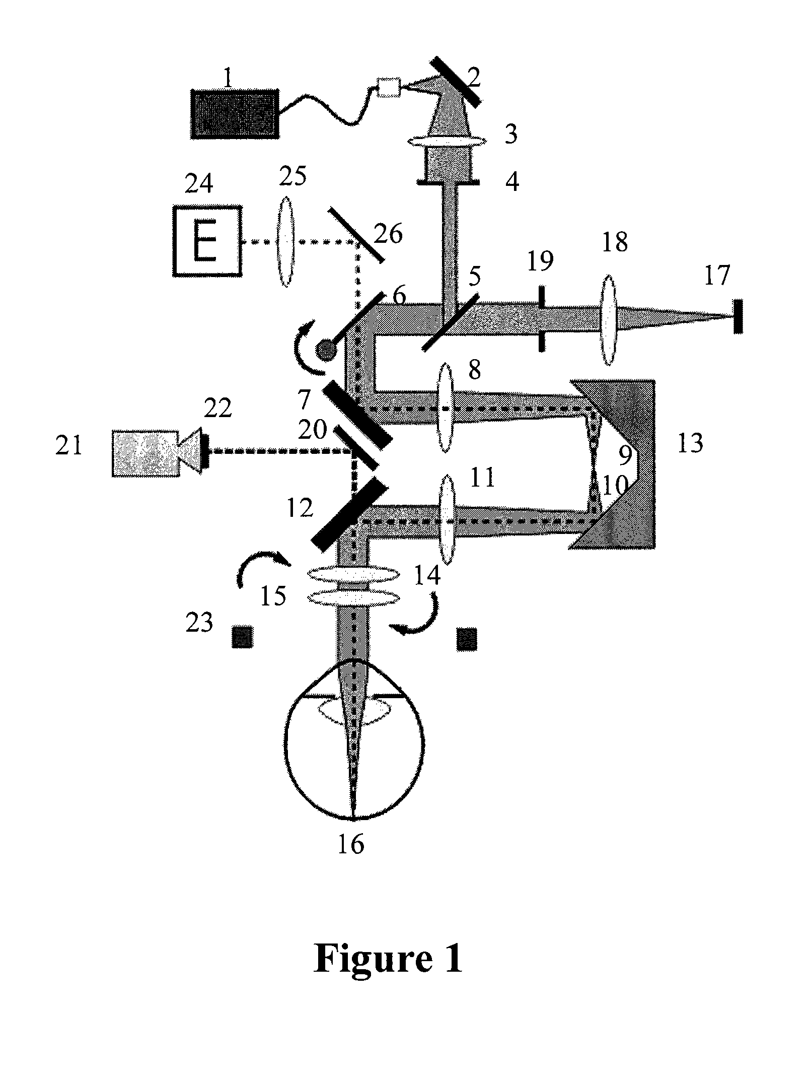
[0044]Continuing with the description of the proposed system, for one embodiment the mentioned means for projecting a point light beam in the retina of an eye of a patient comprise: a point light source; a collimator system; a circular diaphragm which will perform the function of entrance pupil of the system; and a fixation test, the existence of which allows greater comfort for the patient and can consequently facilitate the measurements.

Problems solved by technology

Their impact on visual quality after their correction is therefore very low.
With respect to measuring intraocular scattering, there is no widely accepted robust method which allows the objective measurement thereof on a clinical level.
Consequently, they are difficult and cumbersome to apply in clinical practice.
However, most objective techniques and methods used are theoretical or experimental but not suitable for being adapted to a clinical setting, primarily due to the need to restrict variables affecting the measurement.
In other words, the conditions in which the measurement is performed cannot be transferred to clinical practice as of today.
However, the method developed was not robust to allow use on a clinical level.
One of the main drawbacks of this technique is that the measurement is highly dependent on ocular aberrations.
However the low depolarization level of the retina for scattered light makes the application of the method unfeasible in clinical practice.
All the systems and methods proposed for the objective evaluation of intraocular scattering are not robust, there still being no effective method for being used on a clinical level.

Method used


Image

  • System and method for measuring light scattering in the eyeball or eye region by recording and processing retinal images
  • System and method for measuring light scattering in the eyeball or eye region by recording and processing retinal images
  • System and method for measuring light scattering in the eyeball or eye region by recording and processing retinal images

Examples


Embodiment Construction

[0018]In a first aspect, the present invention relates to a system for measuring light scattering in the eyeball or eye region, conventionally comprising:[0019]means for projecting a point light beam in the retina of an eye of a patient; and[0020]recording means for recording an image of the plane of the retina resulting from the reflected light of said point light in the retina.

[0021]Generally, said means for projecting a point light beam and said recording means are part of a double-pass ophthalmoscopic system.

[0022]Unlike the known proposals, the system proposed by the present invention comprises means for correcting low-order aberrations of the eye prior to said recording so that said image of the plane of the retina is free of the influence of said low-order aberrations.

[0023]Generally, said means for correcting low-order aberrations are provided for correcting defocus and / or astigmatism aberrations.

[0024]A second aspect of the present invention relates to a method for measurin...


PUM


Abstract

The invention relates to a system and method for measuring light diffusion in the eyeball or eye region, by recording and processing retinal images. The inventive system includes a double-pass ophthalmoscopic system having means for correcting low-order aberrations. Said system can be used to record images of the plane of the retina on a CCD camera, the outer part of said images containing information relating to ocular scattering. The aforementioned images can be used to obtain the objective scattering index (OSI), providing the ratio between the energy on the outer part of the image and the energy in the central part, or, alternatively, the modulation transfer function (MTF) area can be used for this purpose once the low frequencies have been filtered. According to the inventive method, the low-order aberrations are corrected before a retinal image or a temporal sequence of retinal images is captured and recorded.

Description

FIELD OF THE INVENTION[0001]The invention herein described is comprised within the field of visual optics, ophthalmology and optometry. In this field, the most important applications are targeted at studies on the aging of the visual system, the early detection and improved diagnosis of pathologies, especially of cataracts, following up on patients subjected to refractive surgery or patients with intraocular lens implants.[0002]The present invention generally relates to a system and a method for measuring light scattering in the eyeball or eye region by recording and processing retinal images resulting from the reflection of a point light beam projected in the retina of a patient, and particularly to a system and a method which enable obtaining and processing images free of the influence of low-order aberrations.BACKGROUND OF THE INVENTION[0003]The retinal image of the human eye can deteriorate due to three causes: diffraction, aberrations and intraocular scattering. Diffraction is ...

Claims


Application Information

Patent Timeline
IPC IPC(8): G06K9/00A61B3/14
CPCA61B3/0025A61B3/1176A61B3/113A61B3/101A61B3/00
Inventor ARTAL SORIANO, PABLOPUJOL RAMO, JAUMEOSCAR LUQUE, SERGIOBENITO GALINDO, ANTONIOPEREZ SANCHEZ, GUILLERMO
Owner UNIV POLITECNICA DE CATALUNYA
Learn More