
Battery pack and balancing method of battery cells

a battery cell and balancing technology, applied in the field of battery cell balancing and battery pack, can solve the problems of battery pack deterioration and lifespan reduction, battery pack may be susceptible to overcharge of a certain amount, and reduce the capacity of the battery pack

Inactive Publication Date: 2010-08-05
SAMSUNG SDI CO LTD
View PDF19 Cites 96 Cited by
  • Summary
  • Abstract
  • Description
  • Claims
  • Application Information

AI Technical Summary

Benefits of technology

[0010]An aspect of exemplary embodiments according to the present invention is to provide battery pack and battery cell-balancing method, which are capable of preventing deep discharge of a certain battery cell without an overdischarge control unit, through the initiation of battery cell balancing near the end of discharge.
[0011]Another aspect of exemplary embodiments according to the present invention is to provide battery pack and battery cell-balancing method, which are capable of preventing damage to the battery cells due to application of a reverse voltage, through the prevention of possible deep discharge of the battery cells.
[0013]In an exemplary embodiment according to the present invention, a balancing method for a battery pack including a plurality of battery cells is provided. According to the method, the battery cells are balanced near an end of discharge. A deep discharge of the battery cells may be prevented without using an overdischarge control unit.
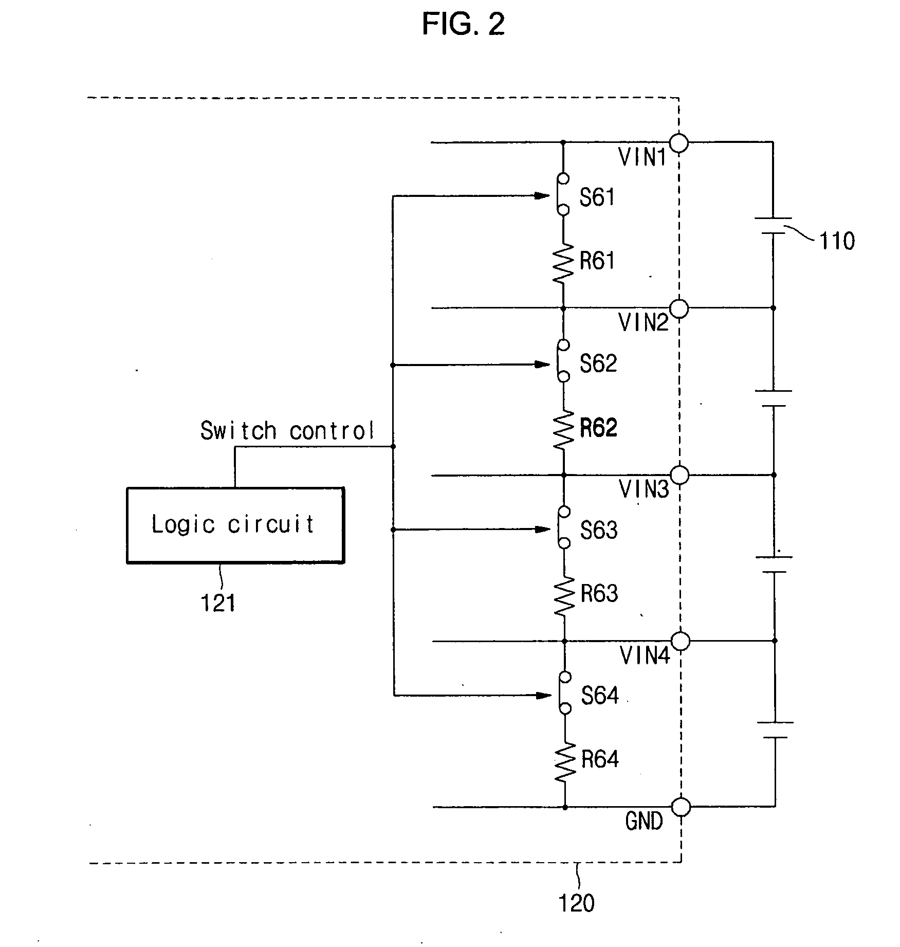
[0025]In another exemplary embodiment according to the present invention, a battery cell balancing system for a battery pack including a plurality of battery cells, is provided. The battery cell balancing system includes: a plurality of balancing switches, each of the balancing switches coupled between positive and negative terminals of a corresponding one of the battery cells; a plurality of balancing resistors, each of the balancing resistors coupled in series with a corresponding one of the balancing switches between the positive and negative terminals of the corresponding one of the battery cells; and a logic circuit for controlling the balancing switches to selectively discharge the battery cells through the respective balancing resistors near an end of discharge, such that the battery cells have same or similar voltages as each other. An overdischarge control unit may be not used while preventing deep discharge of the battery cells.

Problems solved by technology

As a consequence, the battery pack may be susceptible to overcharge of a certain battery cell during the charge process and overdischarge of a certain battery cell during the discharge process.
The occurrences of overcharge or overdischarge of certain battery cells in the battery pack result in a decreased capacity of the battery pack as well as degradation and lifespan reduction of the battery pack.
That is, a conventional battery cell balancing method is not efficient in terms of inhibiting overdischarge of the battery cells.
Further, since the battery pack used in hand-held power tools is not provided with an overdischarge control unit, there is a higher chance for one of its battery cells to be in a deep discharge state.
As discussed above, the battery pack mounted in a special-purpose device such as hand-held power tool is typically not equipped with an overdischarge control unit system.
As a result, there is a high probability that a certain battery cell out of plural battery cells is under deep discharge conditions.
Further, such an overdischarge event may bring about loading of a reverse voltage to a certain battery cell out of a plurality of series-connected battery cells.
In other words, when a reverse voltage is applied to a cylindrical lithium ion battery, the battery is in a highly unstable state, which triggers the operation of safety devices such as CID, for the safety of users.

Method used


Image

  • Battery pack and balancing method of battery cells
  • Battery pack and balancing method of battery cells
  • Battery pack and balancing method of battery cells

Examples


Embodiment Construction

[0045]Now, embodiments of the present invention will be described in more detail with reference to the accompanying drawings.

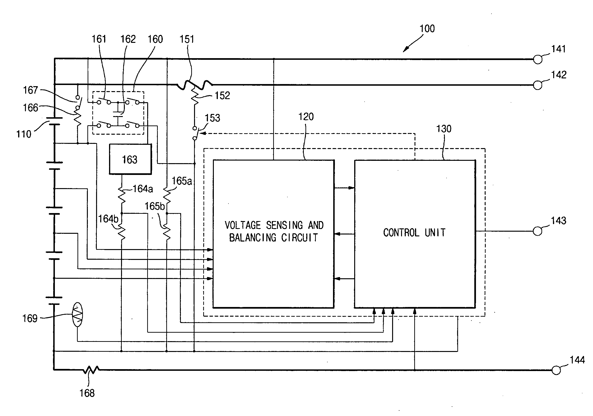
[0046]FIG. 1 is a block diagram illustrating a construction of a battery pack in accordance with one embodiment of the present invention.

[0047]As shown in FIG. 1, a battery pack 100 in accordance with one embodiment of the present invention includes a plurality of rechargeable battery cells 110 coupled in series, a voltage sensing and balancing circuit 120 for sensing voltages of the battery cells and concurrently performing cell balancing, and a control unit 130.

[0048]Each of the battery cells 110 may be a lithium ion battery cell rechargeable up to about 4.2 V, but the present invention is not limited thereto. In addition, the voltage sensing and balancing circuit 120 may include various kinds of analog front ends (AFEs) which are prepared for use in the lithium ion battery, but the present invention is not limited thereto. Further, the control unit 130 may ...


PUM


Abstract

A balancing method for a battery pack includes balancing battery cells near an end of discharge. A deep discharge of the battery cells can be prevented without using an overdischarge control unit. One battery cell balancing method includes: a balancing check condition determination step for determining whether or not a maximum voltage out of voltages of the battery cells is smaller than a reference voltage; a balancing start condition determination step for determining whether or not a residual capacity difference or voltage difference between the individual battery cells exceeds a reference value; a balancing time calculation step for calculating a balancing time for discharging the battery cell that exceeds the reference value; and a balancing operation step for discharging the selected battery cell when the battery cells are under charge or are at rest or when a discharge current of the battery cells is smaller than a reference current.

Description

CROSS-REFERENCE TO RELATED APPLICATION(S)[0001]This applications claims priority to and the benefit of U.S. Provisional Application No. 61 / 149,970 filed Feb. 4, 2009, the entire content of which is incorporated by reference herein.BACKGROUND OF THE INVENTION[0002]1. Field of the Invention[0003]The present invention relates to a battery pack and a balancing method of battery cells.[0004]2. Description of the Related Art[0005]Generally, portable electronic equipment, such as notebook computers and hand-held power tools, is equipped with a rechargeable battery pack as a power source. The battery pack is composed of a plurality of battery cells and a battery monitoring unit for controlling overcharge or overdischarge of individual battery cells and calculating battery capacities.[0006]Individual battery cells of the battery pack exhibit capacity variations which may occur due to various reasons associated with the manufacturing process. For these reasons, the battery pack inevitably und...

Claims


Application Information

Patent Timeline
IPC IPC(8): H02J7/00
CPCH02J7/0016H02J7/345H01M10/441H01M10/482G01R31/36G01R19/16542H01M2010/4271
Inventor YANG, JONGWOONSUSUMU, SEGAWAPARK, INKYUKIM, YONGUK
Owner SAMSUNG SDI CO LTD
Learn More