
System and method for determining stator winding resistance in an ac motor using motor drives

a stator winding resistance and ac motor technology, applied in the direction of motor/generator/converter stopper, dynamo-electric converter control, instruments, etc., can solve the problem of too sensitive to motor parameter variations to provide accurate r/sub>estimation, limit and drawbacks, etc. problem, to achieve the effect of improving the control performance of the motor

Active Publication Date: 2010-08-05
EATON CORP
View PDF19 Cites 60 Cited by
  • Summary
  • Abstract
  • Description
  • Claims
  • Application Information

AI Technical Summary

Benefits of technology

[0009]The present invention provides a system and method for determining the stator winding resistance of AC motors by way of a motor drive. Determination of the stator winding resistance provides for thermal protection of AC motors, improved motor control performance, and condition monitoring of AC motors.

Problems solved by technology

Direct methods, such as the IEEE standard-118, give the most accurate stator resistance estimates, but have limitations and drawbacks due to the fact that resistance is only measured at a certain temperature and the resistance variations due to temperature changes are not considered.
A further drawback of direct measurement methods is that the motor has to be disconnected from service to perform the required tests.
Such model-based methods are non-intrusive and can respond to changes in the cooling conditions but are generally too sensitive to motor parameter variations to provide accurate Rs estimation, due to the fact that the motor parameters may vary under different conditions, such as operating speed, magnetic saturation, etc.
That is, the estimation error of model-based methods can be larger than 20%.
Thermal parameter variation and the difficulty of thermal parameter identification may lead to further inaccuracy in model-based methods.
Although this approach can be accurate and robust to the variations in cooling conditions and motor parameters, it suffers from its intrusive nature, as an extra DC signal injection circuit needs to be installed in series with one of the motor leads.
Additionally, due to the current limits of semiconductor devices, previous signal injection-based methods cannot generally be directly applied to motors beyond 100 hp.

Method used


Image

  • System and method for determining stator winding resistance in an ac motor using motor drives
  • System and method for determining stator winding resistance in an ac motor using motor drives
  • System and method for determining stator winding resistance in an ac motor using motor drives

Examples


Embodiment Construction

[0027]The embodiments of the invention set forth herein relate to a system and method for remote stator winding resistance estimation for thermal protection of induction motors. An AC motor drive is controlled to inject a DC signal into an AC motor line voltage and phase current to the induction motor. A reference voltage and / or reference current command generated by a control system in the AC motor drive is modified to include a DC command therein, thereby modifying a control scheme for a pulse width modulation (PWM) converter in the AC motor drive to inject the DC signal into the AC motor line voltage and phase current. This DC signal is analyzed to determine a stator winding resistance.

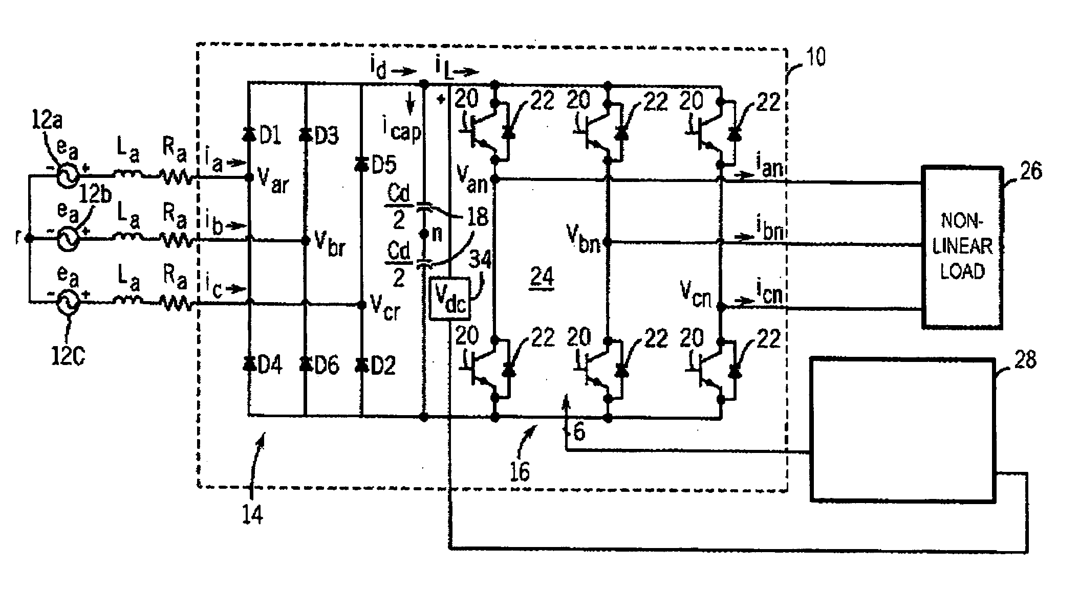
[0028]Embodiments of the invention are directed to AC motor drives encompassing a plurality of structures and control schemes. The general structure of an AC motor drive 10 is shown in FIG. 1. The motor drive 10 may be configured, for example, as an adjustable speed drive (ASD) designed to receive ...


PUM


Abstract

A system and method for determining the stator winding resistance of AC motors is provided. The system includes an AC motor drive having an input connectable to an AC source and an output connectable to an input terminal of an AC motor, a pulse width modulation (PWM) converter having switches therein to control current flow and terminal voltages in the AC motor, and a control system connected to the PWM converter. The control system generates a command signal to cause the PWM converter to control an output of the AC motor drive corresponding to an input to the AC motor, selectively generates a modified command signal to cause the PWM converter to inject a DC signal into the output of the AC motor drive, and determines a stator winding resistance of the AC motor based on the DC signal of at least one of the voltage and current.

Description

GOVERNMENT LICENSE RIGHTS[0001]The present invention was made at least in part with Government support under Contract No. DE-FC36-04GO14000, awarded by the United States Department of Energy. The Government may have certain rights in the invention.BACKGROUND OF THE INVENTION[0002]The present invention relates generally to alternating current (AC) induction motors and, more particularly, to a system and method for determining the stator winding resistance of AC motors by way of a motor drive, for thermal protection of AC motors, improving motor control performances, and condition monitoring of AC motors.[0003]The usage of motor drives in various industries has recently become more prevalent based on the increasing need for energy savings and control flexibility in motor operation. Based on these needs, improvements in motor control performance have become increasingly important. One factor of improved motor control performance is the accuracy of motor parameter estimation, which is o...

Claims


Application Information

Patent Timeline
IPC IPC(8): H02P27/00H02P23/14
CPCH02P21/145H02P21/141H02P21/16
Inventor LU, BINHABETLER, THOMAS G.ZHANG, PINJIA
Owner EATON CORP
Learn More