
Fret detection method and device

Inactive Publication Date: 2010-08-05
MITSUI ENG & SHIPBUILD CO LTD
View PDF2 Cites 9 Cited by
  • Summary
  • Abstract
  • Description
  • Claims
  • Application Information

AI Technical Summary

Benefits of technology

[0027]According to the present invention, two types of lasers are used for exciting the first molecule and the second molecule, and intensities of the lasers are modulated at predetermined frequencies. In addition, frequencies are respectively shifted in the intensity modulations for discriminating different types of fluorescences. After reception of fluorescences to be emitted in response to the lasers, the phase delays are further computed for the fluorescences emitted from the second molecule at two frequencies using the fact that frequencies in the intensity modulations are different from each other. FRET is then detected based on the phase delays. The above signal processing can be executed in a short period of time. Therefore, the sample can be efficiently measured in a short period of time, and a result of FRET detection can be statistically established.
[0028]Especially, a ratio of the aforementioned two phase delays largely varies depending on generation of FRET. Accordingly, FRET can be precisely detected by using the ratio even if the FRET efficiency is low. Furthermore, when the present invention is applied to the flow cytometer, FRET can be detected by processing a signal of fluorescence emitted from the sample passing through a measurement point at a constant speed. Therefore, the sample can be efficiently measured in a short period of time, and a result of FRET detection can be statistically established. Moreover, interactions between target molecules can be efficiently researched.BRIEF EXPLANATION OF DRAWINGS
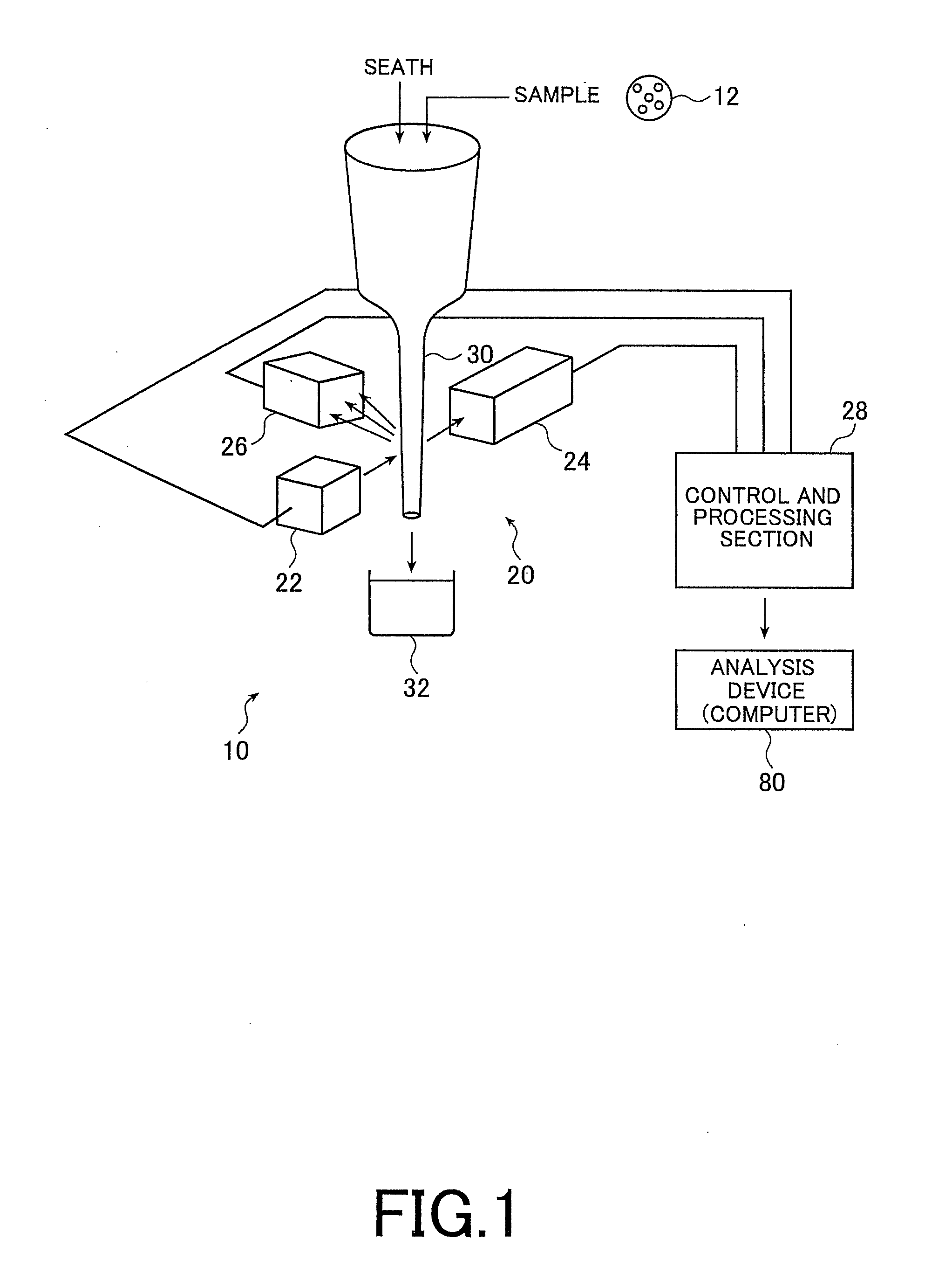
[0029]FIG. 1 is a schematic configuration diagram of a flow cytometer, which is an embodiment of a FRET detection device of the present invention.
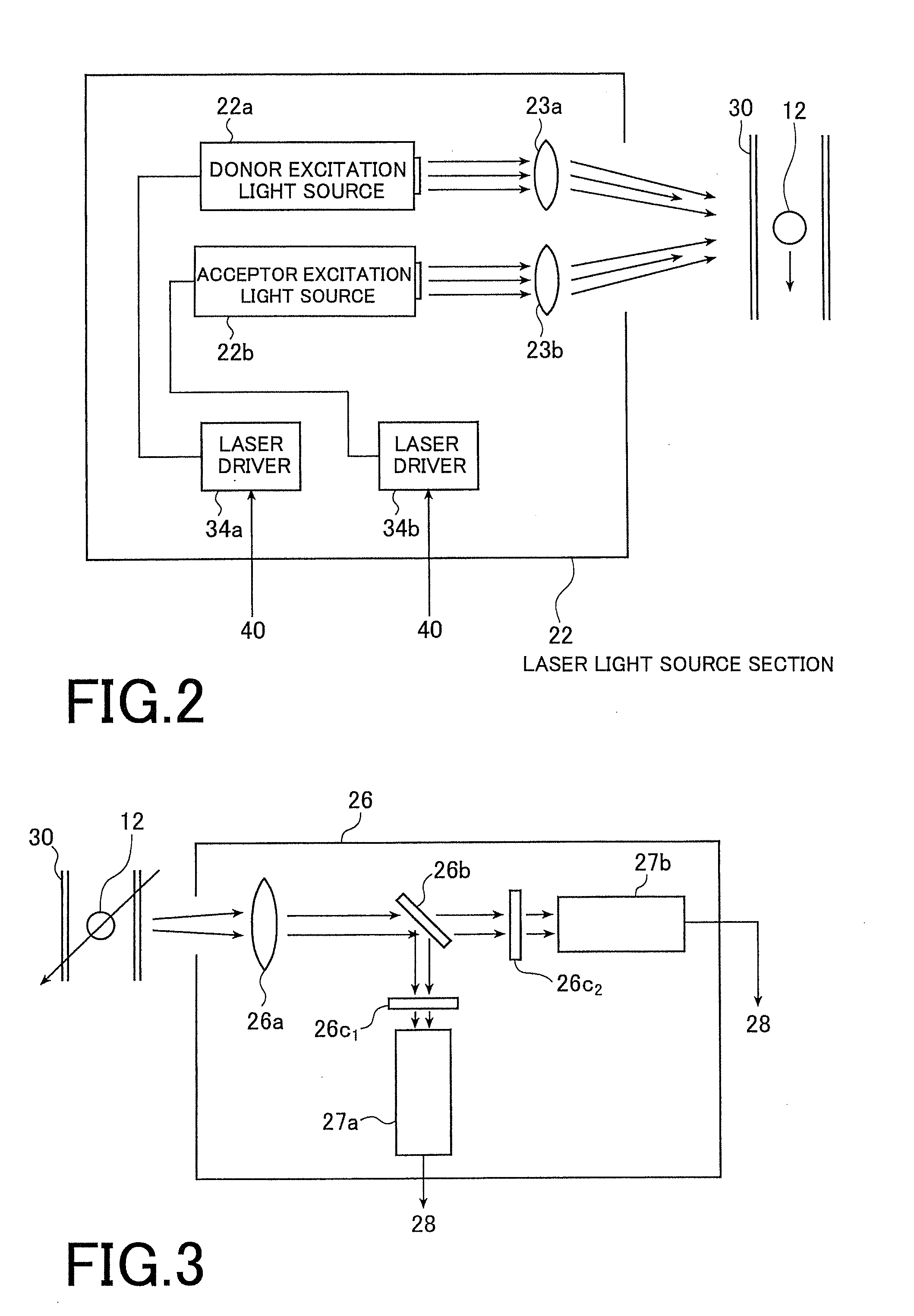
[0030]FIG. 2 is a schematic configuration diagram of a laser light source unit in the flow cytometer illustrated in FIG. 1.
[0031]FIG. 3 is a schematic configuration diagram of a light receiving unit in the flow cytometer illustrated in FIG. 1.
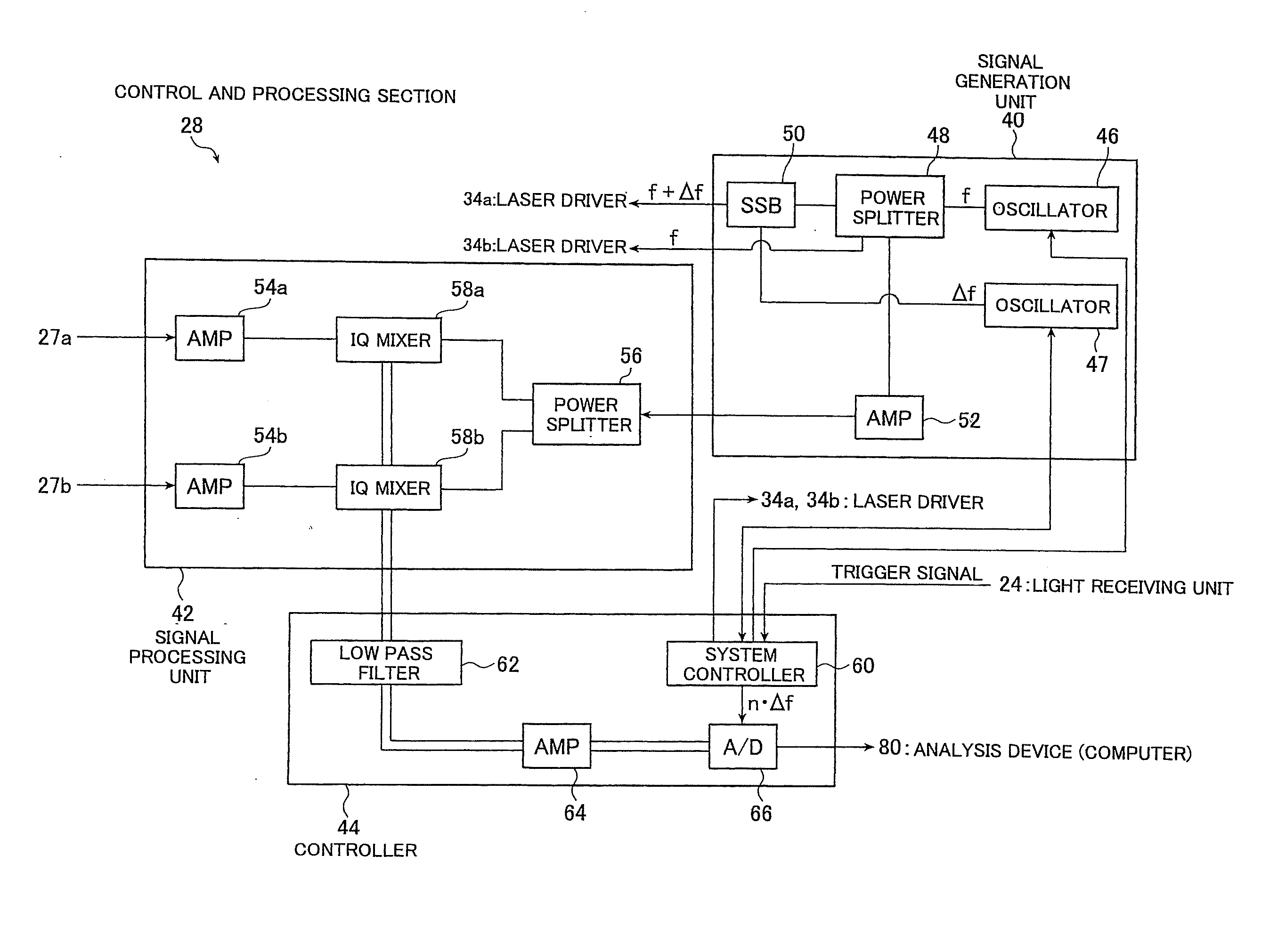
[0032]FIG. 4 is a schematic configuration diagram of a control and processing section in the flow cytometer illustrated in FIG. 1.

Problems solved by technology

In the method, however, the number of samples (e.g., cells) is limited to at most several dozen for detecting FRET in a short period of time.
In other words, it is difficult to statistically analyze a large number of cells as analysis targets in a short period of time.

Method used


Image

  • Fret detection method and device
  • Fret detection method and device
  • Fret detection method and device

Examples


Embodiment Construction

[0068]A method of and a device for detecting FRET of the present invention will be hereinafter explained in detail.

[0069]FIG. 1 is a schematic configuration diagram of a flow cytometer 10, which is an embodiment of a FRET detection device of the present invention.

[0070]The flow cytometer 10 is configured to determine whether or not energy of a first molecule (donor molecule) transfers to energy of a second molecule (acceptor molecule) by receiving fluorescence emitted from the acceptor molecule when the acceptor is excited by fluorescence emitted from the donor molecule. The donor molecule emits fluorescence when being excited by laser irradiation. To detect the energy transfer, intensity modulation is executed for lasers to be irradiated respectively to the donor molecule and the acceptor molecule at predetermined frequencies. The present invention has a feature that FRET generation is detected by measuring phase delays of fluorescences to be emitted in response to laser irradiatio...


PUM


Abstract

When FRET (Fluorescence Resonance Energy Transfer) detection of a large number of samples is performed in a short time for a sample consisting of a donor molecule and an acceptor molecule, the donor molecule is irradiated at first with first laser light used for exciting a donor molecule subjected to intensity modulation at a frequency of f+Δf, the accepter molecule is irradiated with second laser light used for exciting an acceptor molecule subjected to intensity modulation at a frequency of f, and fluorescence emitted from the accepter molecule is received. From a fluorescence signal thus received, a first signal component of fluorescence emitted from the accepter molecule through FRET, and a second signal component of fluorescence emitted from an accepter molecule excited through irradiation with the second laser light are extracted. Phase lags of the first and second signal components thus extracted are then calculated and the presence of generation of FRET is judged based on these phase lags.

Description

FIELD OF INVENTION[0001]The present invention relates to a method of and a device for detecting FRET (fluorescence resonance energy transfer) that energy of a first molecule transfers to energy of a second molecule, by receiving fluorescence emitted from the second molecule when the second molecule is excited by fluorescence of the first molecule to be excited by laser irradiation. Specifically, the present invention relates to a FRET detection technology for detecting interaction between a pair of a donor molecule (fluorescence molecule) and an acceptor molecule (fluorescence molecule) using fluorescence.BACKGROUND ART[0002]An analysis of protein function has been recently important as the post-genome related technology in the medical industry, the pharmaceutical industry and the food industry. Especially to analyze actions of cells, research is required for interactions (binding and separation) between a type of protein and another type of protein (or a low molecule compound), whi...

Claims


Application Information

Patent Timeline
IPC IPC(8): G01N21/64
CPCG01N2021/6419G01N21/6428G01N21/64G01N33/483
Inventor KIMURA, NORIAKINAKADA, SHIGEYUKIDOI, KYOUJI
Owner MITSUI ENG & SHIPBUILD CO LTD
Learn More