Temperature control device of electric heater using thermo-sensitive resin and safety device thereof
a technology of thermo-sensitive resin and temperature control device, which is applied in the direction of ohmic-resistance heating, ohmic-resistance heating details, electrical apparatus, etc., can solve the problems of not accurately sensing the change in temperature, unable to reliably detect the overheating, and the folding portion may be overheated compared to the unfolded portion
- Summary
- Abstract
- Description
- Claims
- Application Information
AI Technical Summary
Benefits of technology
Problems solved by technology
Method used
Image
Examples
embodiment 1
[0089]Below, a first embodiment of the present invention will be described by referring to FIG. 10.
[0090]A temperature control device according to a first embodiment of the present invention is constituted by a power supply unit 11, a temperature sensing unit 12, an overheating protection unit 15, a signal control unit 13, a power control unit 14 and a sleep mode unit 10.
[0091]The power supply unit, which is constituted by a rectifier that converts alternating current (AC) to direct current (DC), is a circuit that rectifies an electric current from AC to DC and provides a direct current voltage (Vcc) so as to operate the control circuit.
[0092]The temperature sensing unit is a circuit that generates a control signal by detecting a change in electric current, which flows in a direction opposite to the power control component (SCR), through the use of a thermo-sensitive resin (NTC) on alternate temperature sensing cycles, during which a reverse voltage is applied to the power control c...
embodiment 2
[0173]In this embodiment, a temperature control device of an electric heater, which uses a thermo-sensitive insulation resin with the same technical principle as that of the first embodiment of the present invention, has a structure in which a magnetic field radiating to the outside is offset by allowing the heating current to reversely flow from the heating wire to the sensing wire (that is, the electric currents flowing through the heating wire and the sensing wire flow in opposite directions so as to offset the magnetic field).
[0174]Below, the configuration of the present invention will be described with reference to the accompanying drawings.
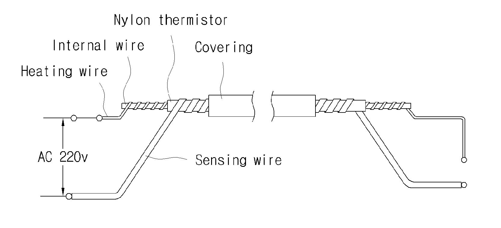
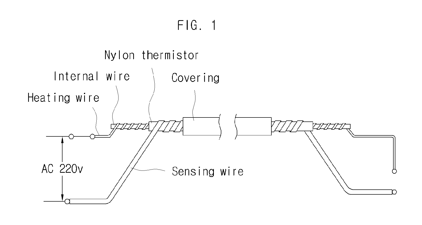
[0175]A heating cable that is used in the present embodiment has the same structure as that of FIG. 1. In this embodiment, however, the sensing wire can be used as a heating wire in a normal use.
[0176]In this embodiment, the sensing wire is used as a second heating wire.
[0177]The circuit shown in FIG. 11 has a structure in which one end part...
embodiment 3
[0189]A third embodiment of the present invention shown in FIG. 12 presents a circuit that is designed for implementing the second embodiment of the present invention in a more economical and reliable way.
[0190]In this embodiment, each of the heating cycle and the sensing cycle becomes a half-cycle, and the first and second switching control components are used as a rectifying component. As a result, the overall number of circuit components can be reduced, and this arrangement can make a simpler and more reliable circuit.
[0191]FIG. 12 shows a circuit of a temperature control device according to the third embodiment of the present invention.
[0192]The heating cable of FIG. 12 has the same structure as that of FIG. 1. For better understanding, however, the heating wire of FIG. 1 is referred to as a first heating wire, and the sensing wire of FIG. 1 is referred to as a second heating wire.
[0193]In other words, a heating cable that is constituted by two heating wires and one thermo-sensi...
PUM
 Abstract
Description
Claims
Application Information
 - R&D
- Intellectual Property
- Life Sciences
- Materials
- Tech Scout
- Unparalleled Data Quality
- Higher Quality Content
- 60% Fewer Hallucinations
Browse by: Latest US Patents, China's latest patents, Technical Efficacy Thesaurus, Application Domain, Technology Topic, Popular Technical Reports.
© 2025 PatSnap. All rights reserved.Legal|Privacy policy|Modern Slavery Act Transparency Statement|Sitemap|About US| Contact US: help@patsnap.com


