Image processing apparatus, printing apparatus, and image processing method
a technology of image processing and printing apparatus, which is applied in the field of image processing apparatus, printing apparatus, and image processing method, can solve the problems of deteriorating the quality of printed images, affecting the dispersion properties of dots, and a new view of density change or uneven density due to a shift of print position (registration) per scan, etc., and achieves the effect of reducing the processing to each divided imag
- Summary
- Abstract
- Description
- Claims
- Application Information
AI Technical Summary
Benefits of technology
Problems solved by technology
Method used
Image
Examples
first embodiment
[0047]FIG. 3 is a perspective view explaining a schematic structure of a serial type inkjet printing apparatus used in a first embodiment of the present invention. A print head 105 is mounted on a carriage 104 that moves at a constant speed in a main scan direction and ejects ink according to print data in a frequency corresponding to the constant speed. When one time of scan is completed, a conveying roller 704 and an auxiliary roller 703 rotate and a print medium P held between these rollers and between a feeding roller 705 and an auxiliary roller 706 is conveyed in a sub scan direction by an amount corresponding to a print width by the print head 105. This scan and the conveying operation are intermittently repeated to print an image on the print medium P step by step. The sub scan direction will be described later in processing of image data.
[0048]The print head 105 includes print heads of black (K), cyan (C), magenta (M) and yellow (Y) which are located in a main scan direction...
second embodiment
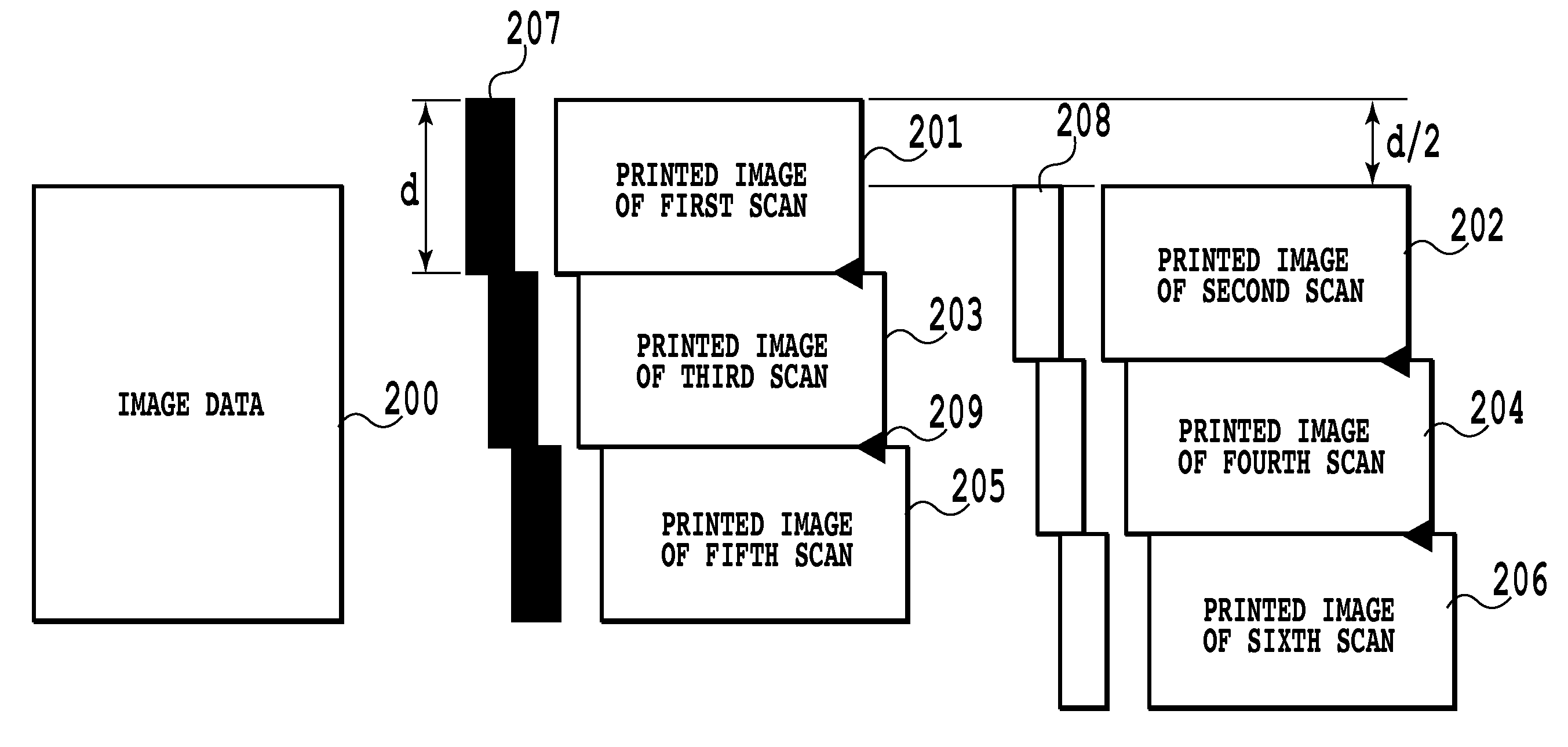
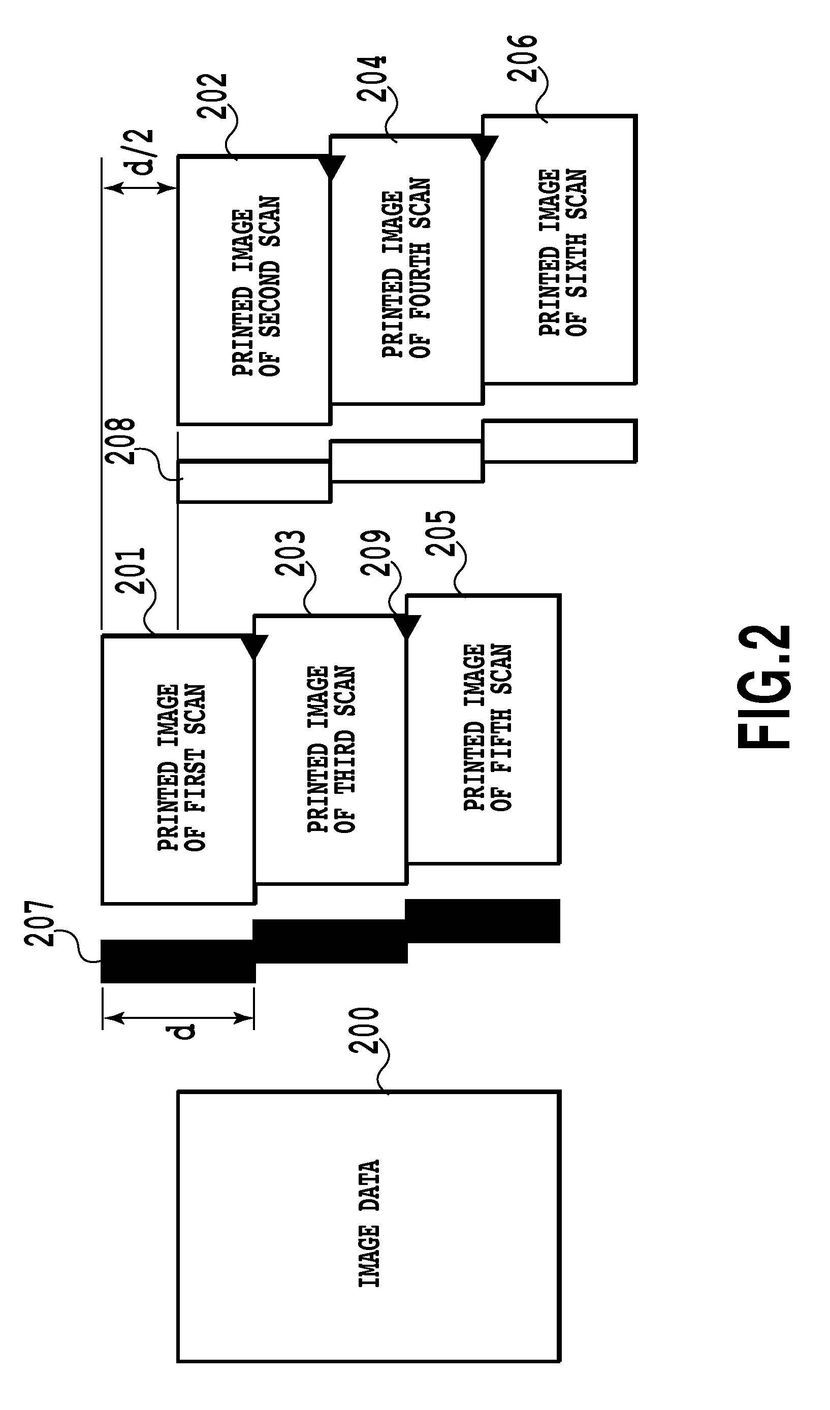
[0067]The present embodiment relates to an example of applying the error generated at the time of executing the gradation lowering processing to the multi-valued print data to the multi-valued print data after two scans are performed. That is, for example, as seen also from FIG. 4, in a case of a multi-pass printing of a two-pass, the boundary between areas printed by the respective scans is a boundary between areas printed by twice of the scans with one scan interposed in between, such as between an area 401 and an area 403 or between an area 402 and an area 404. In the present embodiment, the error is diffused through this boundary to the other area.
[0068]In addition, in the present embodiment, an area for which the gradation lowering processing is executed is set to be data (“d” pixels) corresponding to one scan and successive data (“α” pixels). Therefore, for example, continuity of dot arrangements of respective areas printed with the multi-valued print data 401 and the multi-va...
third embodiment
[0074]The present embodiment takes a multi-pass print of four-pass as an example where an error generated at the time of executing gradation lowering processing to the multi-valued print data is stored in the same way as in the first embodiment. Specially the stored error is divided to be used for the multi-valued print data after one scan and the multi-valued print data after two scans in respective predetermined ratios (⅓ to the multi-valued print data after one scan and ⅔ to the multi-valued print data after two scans). It should be noted that the printing operation, the processing direction of the error diffusion process and the error diffusion matrix are the same as those in the aforementioned first embodiment.
[0075]FIG. 13 is a diagram corresponding to FIG. 4 according to the first embodiment. In the present embodiment, because of the multi-pass printing of the four-pass, each multi-valued print data generated in the multi-valued print data generation section 503 (FIG. 5) are ...
PUM
 Abstract
Description
Claims
Application Information
 - R&D
- Intellectual Property
- Life Sciences
- Materials
- Tech Scout
- Unparalleled Data Quality
- Higher Quality Content
- 60% Fewer Hallucinations
Browse by: Latest US Patents, China's latest patents, Technical Efficacy Thesaurus, Application Domain, Technology Topic, Popular Technical Reports.
© 2025 PatSnap. All rights reserved.Legal|Privacy policy|Modern Slavery Act Transparency Statement|Sitemap|About US| Contact US: help@patsnap.com


