
Electroosmotic pump with improved gas management

a technology of electroosmotic pump and gas management, which is applied in the direction of electrodialysis, diaphragms, refrigeration components, etc., can solve the problems of affecting the efficiency of eo pumps, affecting the degree to which eo pumps can be miniaturized, and undesirable design constraints, etc., to achieve efficient gas removal, small scale size, and high flow rate

Active Publication Date: 2010-07-29
ARIZONA STATE UNIVERSITY +1
View PDF32 Cites 12 Cited by
  • Summary
  • Abstract
  • Description
  • Claims
  • Application Information

AI Technical Summary

Benefits of technology

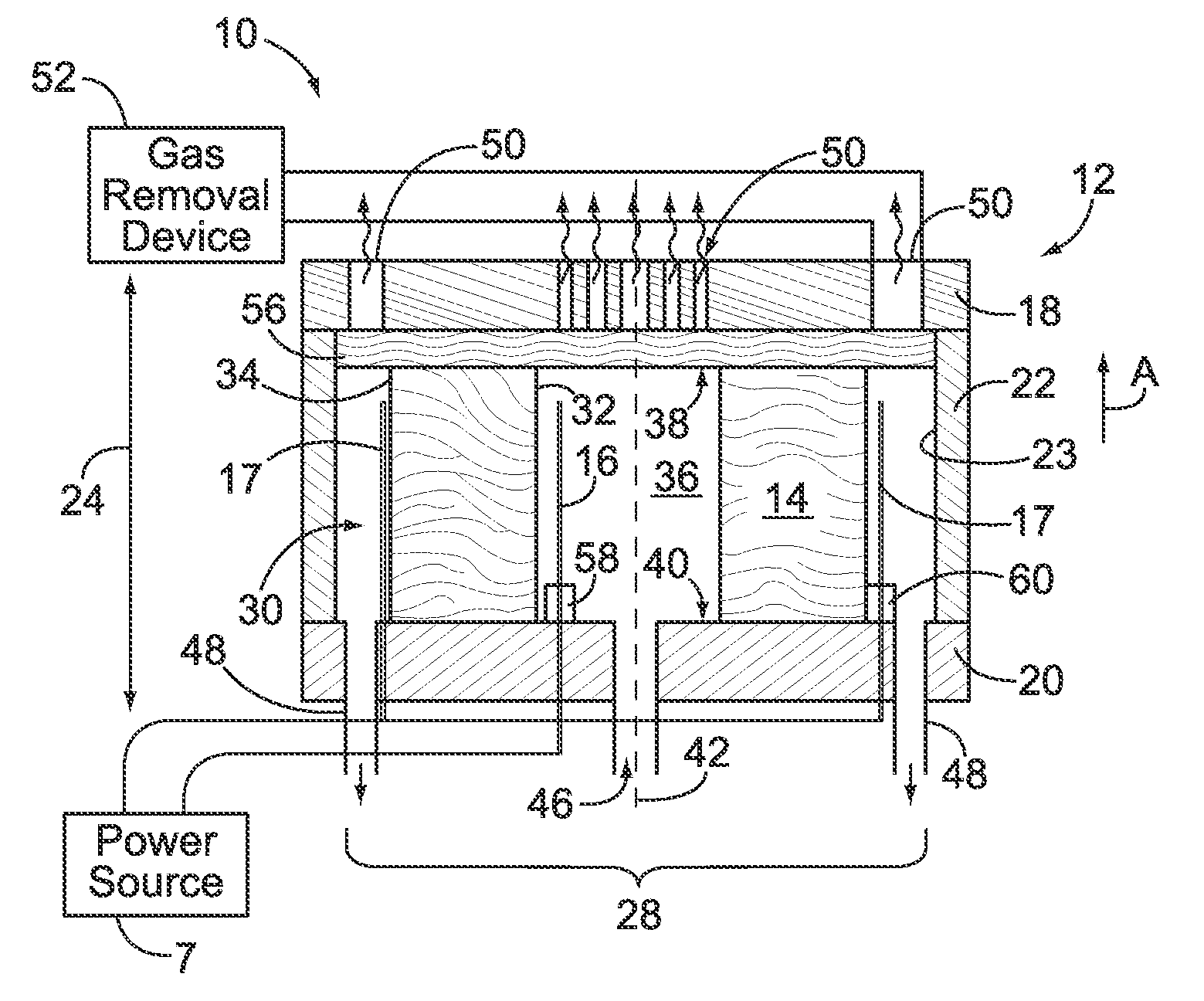
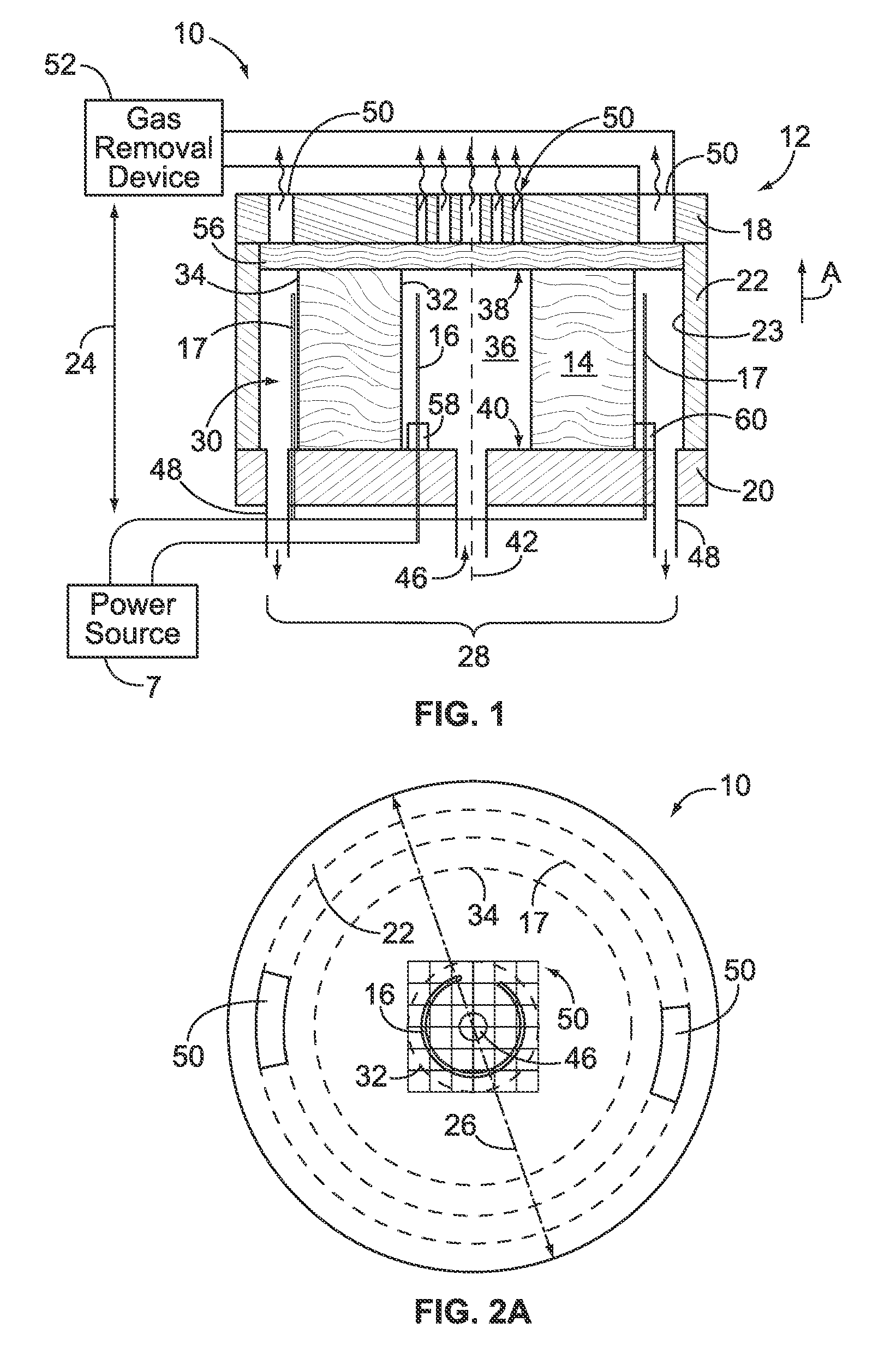
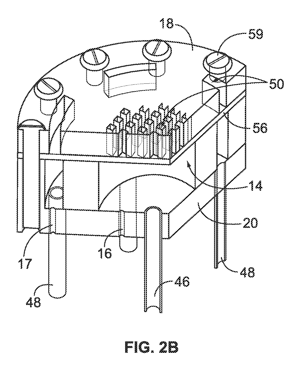
The patent describes an electroosmotic pump that uses a porous core medium and electrodes to induce fluid flow. The pump includes a housing with a pump cavity and a gas removal device. The gas generated when the electrodes induce flow of fluid through the porous core medium can be removed through the gas removal device. The pump can also include a vacuum cavity and a core retention member with electrodes located within it. The electrodes induce flow of fluid through the porous core medium, and the gas generated can be removed through the gas removal device or the vacuum cavity. The technical effects of this design include improved gas removal, reduced attachment of gas bubbles, and improved pump performance.

Problems solved by technology

When gas builds up excessively it will detract from the pump performance.
However, conventional EO pumps have exhibited certain disadvantages.
For example, the gas management techniques used by existing EO pumps can place undesirable design constraints on the degree to which the EO pumps can be miniaturized.
As the gas to medium area ratio increases, the flow capacity reduces and in some cases the flow rate may be undesirably low.
The flow capacities and pump volumes of conventional EO pumps render such EO pumps impractical for use in certain small scale applications, such as in certain biochemical analyses.
Furthermore, these new technologies frequently depend upon heavily automated processes that must perform at a high level of precision.
Some of these devices have movable parts that may disturb or negatively affect the reading and analyzing of the fluorescent signals.
Furthermore, after one or more cycles the pumps may need to be exchanged or cleaned thereby increasing the amount of time to complete a run that consists of several cycles.
Miniaturization of conventional EO pumps has been constrained such that the full potential of EO flow for pumping fluids for analytical analyses such as nucleic acid sequencing reactions has not been met.
However, each of the above methods may have undesirable limitations.

Method used


Image

  • Electroosmotic pump with improved gas management
  • Electroosmotic pump with improved gas management
  • Electroosmotic pump with improved gas management

Examples


Embodiment Construction

[0061]In accordance with at least certain embodiments described herein, one or more of the following technical effects may be achieved. Embodiments of the present invention provide an EO pump that affords efficient management of gas in real-time while generated as a byproduct of the electroosmotic process, such as the hydrogen gas and oxygen gas that are generated due to the splitting of water molecules at the electrodes that drive fluid flow. Through efficient gas management, embodiments of EO pumps described herein remove the gas at a rate sufficient to maintain desirable flow rates and prevent or at least hinder passage of the gas to downstream components within a desired application. Embodiments of the EO pumps described herein enable fluids to be pumped within pumping structures having an extremely small form factor and flow parameters that satisfy the design conditions associated with flow cells for biochemical assays, such as sequencing by synthesis reactions and the like.

[00...


PUM

PropertyMeasurementUnit
depthaaaaaaaaaa
depthaaaaaaaaaa
depthaaaaaaaaaa

Abstract

An electroosmotic (EO) pump is provided that includes a housing having a pump cavity, a porous core medium and electrodes. The porous core medium is positioned within the pump cavity to form an exterior reservoir that extends at least partially about an exterior surface of the porous core medium. The porous core medium has an open inner chamber provided therein. The inner chamber represents an interior reservoir. The electrodes are positioned in the inner chamber and are positioned proximate the exterior surface. The electrodes induce flow of a fluid through the porous core medium between the interior and exterior reservoirs, wherein a gas is generated when the electrodes induce flow of the fluid. The housing has a fluid inlet to convey the fluid to one of the interior reservoir and the exterior reservoir. The housing has a fluid outlet to discharge the fluid from another of the interior reservoir and the exterior reservoir. The housing has a gas removal device to remove the gas from the pump cavity.

Description

CROSS REFERENCE TO RELATED APPLICATIONS[0001]This application claims the benefit of U.S. Provisional Application No. 61 / 118,073, filed Nov. 26, 2008 and having the same title, which is hereby incorporated by reference in the entirety.BACKGROUND OF THE INVENTION[0002]The present invention relates generally to electroosmotic pumps and more particularly to electroosmotic pumps for use in biochemical analysis system.[0003]Recently, electroosmotic (EO) pumps have been proposed for use in a limited number of applications. An EO pump generally comprises a fluid chamber that is separated into an inlet reservoir and an outlet reservoir by a planar medium forming a dividing wall there between. The medium may also be referred to as a frit. An anode and a cathode are provided within the inlet and outlet reservoirs, respectively, on opposite sides of the medium. When an electrical potential is applied across the anode and cathode, the medium forms a pumping medium and fluid is caused to flow thr...

Claims


Application Information

Patent Timeline
Patent Type & Authority Applications(United States)
IPC IPC(8): B01D57/02F04B19/00B01D61/46B81B7/02C12Q1/68B01J19/00G01N27/447
CPCF04B19/00Y10T436/2575F04B37/10
Inventor POSNER, JONATHANSALLOUM, KAMILLEBL, MICHALREED, MARKBUERMANN, DALEHAGE, MATTHEWCRANE, BRYANHEINER, DAVIDKAIN, ROBERT
Owner ARIZONA STATE UNIVERSITY
Learn More