Continuously-Arranged Sensor System, Network Unit, and Sensor Unit

Inactive Publication Date: 2010-07-22
KEYENCE
View PDF7 Cites 8 Cited by
  • Summary
  • Abstract
  • Description
  • Claims
  • Application Information

AI Technical Summary

Benefits of technology

[0010]The configuration described in Japanese Patent Application Laid-Open No. 2004-295276 allows the determination signal of each sensor unit to be transmitted via the network unit to the host control apparatus through the parallel transmission line without delay. However, the more sensor units are arranged, the more wirings should be connected, and therefore, there is a limitation on the number of sensors that can be connected.
[0025]In the continuously-arranged sensor system according to the present invention, the determination signal of each sensor unit is transmitted to the network unit side via the serial transmission unit. The time information at which data is updated is simultaneously stored at this moment, so that the time of the determination signal can be obtained. Therefore, the network unit or the host control apparatus can centrally manages operational state of each sensor unit. The network unit can manage the operational state of each sensor unit on the basis of the received information. Further, required data are transmitted to the host control apparatus, and therefore, it is possible to centrally manage the operational state of each sensor unit.

Problems solved by technology

However, the more sensor units are arranged, the more wirings should be connected, and therefore, there is a limitation on the number of sensors that can be connected.
As shown in Japanese Patent Application Laid-Open No. 2003-97983, when the determination signal of the sensor is transmitted as a serial signal, a delay in time occurs in the transmission of the determination signal to the host control apparatus.
Therefore, there is a drawback in that it is difficult for the host control apparatus to use the determination signal of each sensor.

Method used


Image

  • Continuously-Arranged Sensor System, Network Unit, and Sensor Unit
  • Continuously-Arranged Sensor System, Network Unit, and Sensor Unit
  • Continuously-Arranged Sensor System, Network Unit, and Sensor Unit

Examples


first embodiment

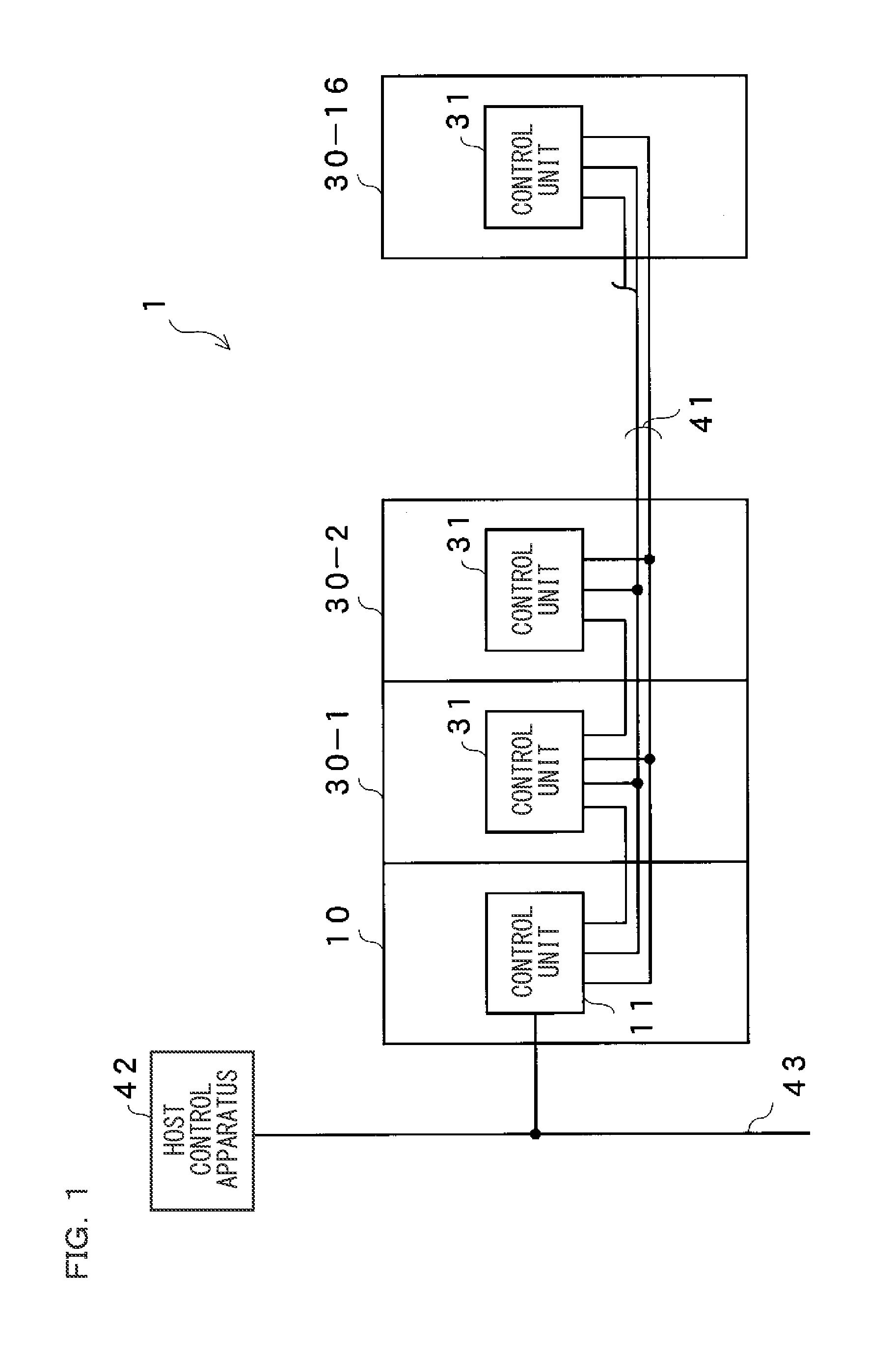
[0054]FIG. 1 is a figure showing an entire configuration of a continuously-arranged sensor system according to the first embodiment of the present invention. The continuously-arranged sensor system 1 includes at least one sensor unit connected to a network unit 10. In this embodiment, a series of sixteen sensor units 30-1 to 30-16 are connected to the network unit 10. These units are electrically connected via a serial transmission line 41 including at least two serial transmission lines. Hereinafter, a direction toward the network unit 10 is referred to as upstream direction, and a direction toward the sensor unit 30-16 is referred to as downstream direction. The network unit 10 is adapted to collect signals transmitted from the sensor units 30-1 to 30-16 and to transmit a necessary signal to a host control apparatus 42, and is connected to the host control apparatus 42 via a feed bus 43.

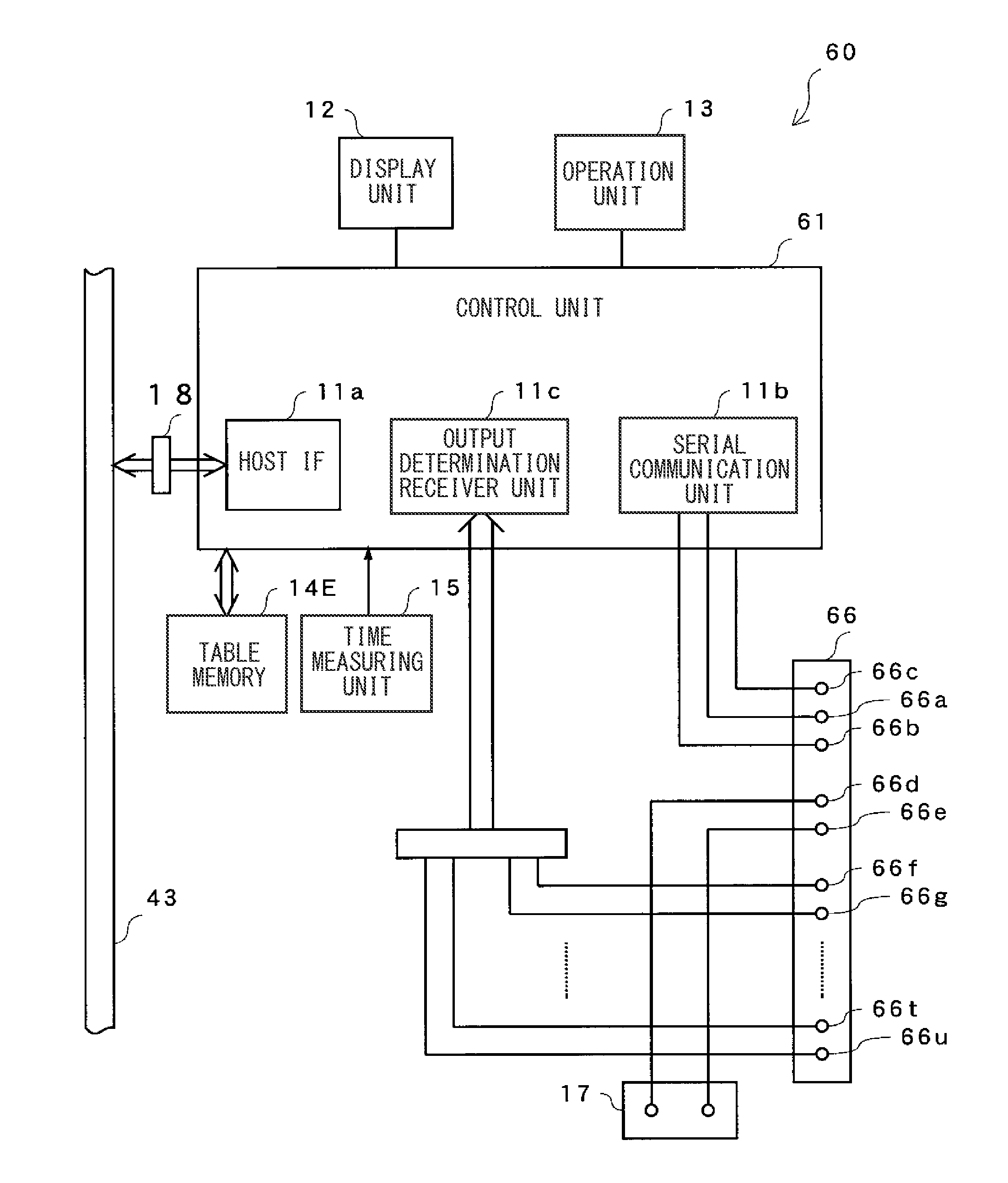
[0055]Subsequently, each unit will be described in detail. FIG. 2 is a block diagram showing an...

second embodiment

[0093]Subsequently, a continuously-arranged sensor system according to the second embodiment of the present invention will be described. The configurations of the present embodiment are the same as those of the first embodiment except for the data contents stored in the table memory 14B. In the present embodiment, the network unit 10 does not transmit the data transmission command to each sensor unit. When the determination signal changes, the determination unit 31b of each sensor unit transmits an ON determination signal or an OFF determination signal to the network unit 10 via the serial transmission line 41. The control unit 11 of the network unit 10 receives the change of the determination signal from any one of the sensor units, the control unit 11 simultaneously writes, to the table memory 14B, either ON state or OFF state and the time obtained from the time measuring unit 15 indicating a time at that moment as a change time. Therefore, the table memory 14B can be generated as...

third embodiment

[0096]Subsequently, a continuously-arranged sensor system according to the third embodiment of the present invention will be described. The configurations of the present embodiment are the same as those of the second embodiment except for the data contents stored in the table memory 14C. In the present embodiment, when the determination signal changes, the determination unit 31b of each sensor unit transmits an ON determination signal or an OFF determination signal to the network unit 10 via the serial transmission line 41. The control unit 11 of the network unit 10 updates the table memory 14C when the control unit receives the change of the determination signal of the sensor unit. More specifically, as shown in FIG. 4C, a rising time at which the output of each sensor unit is turned on and a fall time at which the output thereof is turned off are stored. When a further change of the output state is transmitted via the serial transmission line 41, the rising time and the fall time ...


PUM


Abstract

A continuously-arranged sensor system is provided that can recognize a time of a determination signal provided by each sensor unit so that a host control apparatus can use the time to perform timing control. The continuously-arranged sensor system includes a network unit and a plurality of sensor units, which are connected by a serial transmission line. In accordance with a command sent from the network unit, each sensor unit transmits the determination signal to the network unit via the serial transmission line. The network unit stores the time information and the determination information to a table memory.

Description

CROSS-REFERENCE TO RELATED APPLICATIONS[0001]The present application claims foreign priority based on Japanese Patent Application No. 2009-8564, filed Jan. 19, 2009, the contents of which is incorporated herein by reference.BACKGROUND OF THE INVENTION[0002]1. Field of the Invention[0003]The present invention relates to a continuously-arranged sensor system for monitoring a state of an object to be detected, and also relates to a network unit and a sensor unit used for the continuously-arranged sensor system.[0004]2. Description of the Background Art[0005]In a manufacturing process in an automated manufacturing line, a process state of a workpiece is monitored in order to reliably process the workpiece. Therefore, in the automated manufacturing line, many sensors are arranged in proximity to the workpiece (object to be detected) so as to monitor the process state, and the workpiece is processed while a determination signal of each sensor is monitored.[0006]In this kind of sensor syst...

Claims


Application Information

Patent Timeline
IPC IPC(8): G06F15/00
CPCH04L12/40013
Inventor FUKUMURA, KOJIKAWANAKA, MASASHI
Owner KEYENCE
Why Eureka
Try Eureka