Valve timing controller
- Summary
- Abstract
- Description
- Claims
- Application Information
AI Technical Summary
Benefits of technology
Problems solved by technology
Method used
Image
Examples
first embodiment
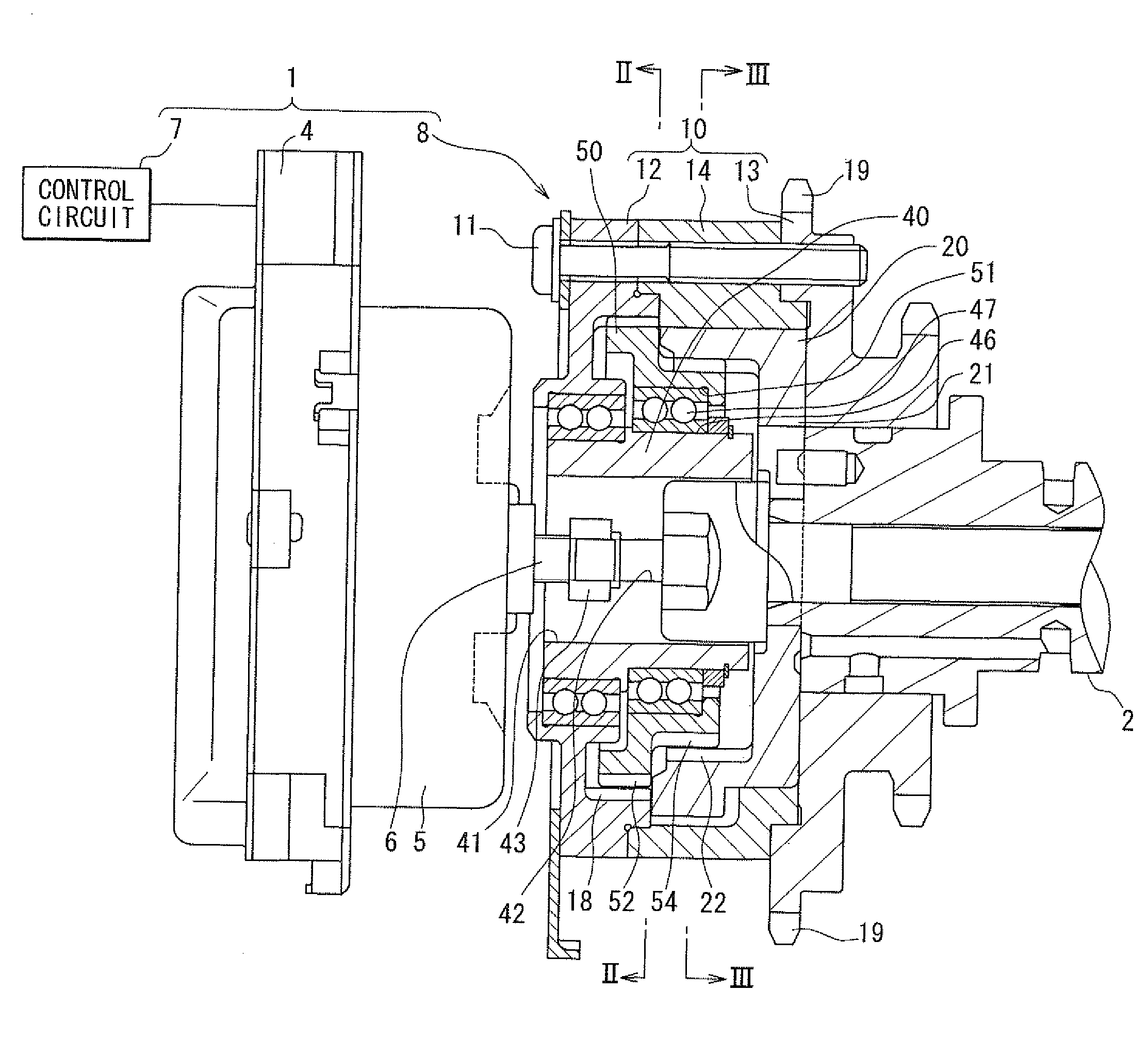
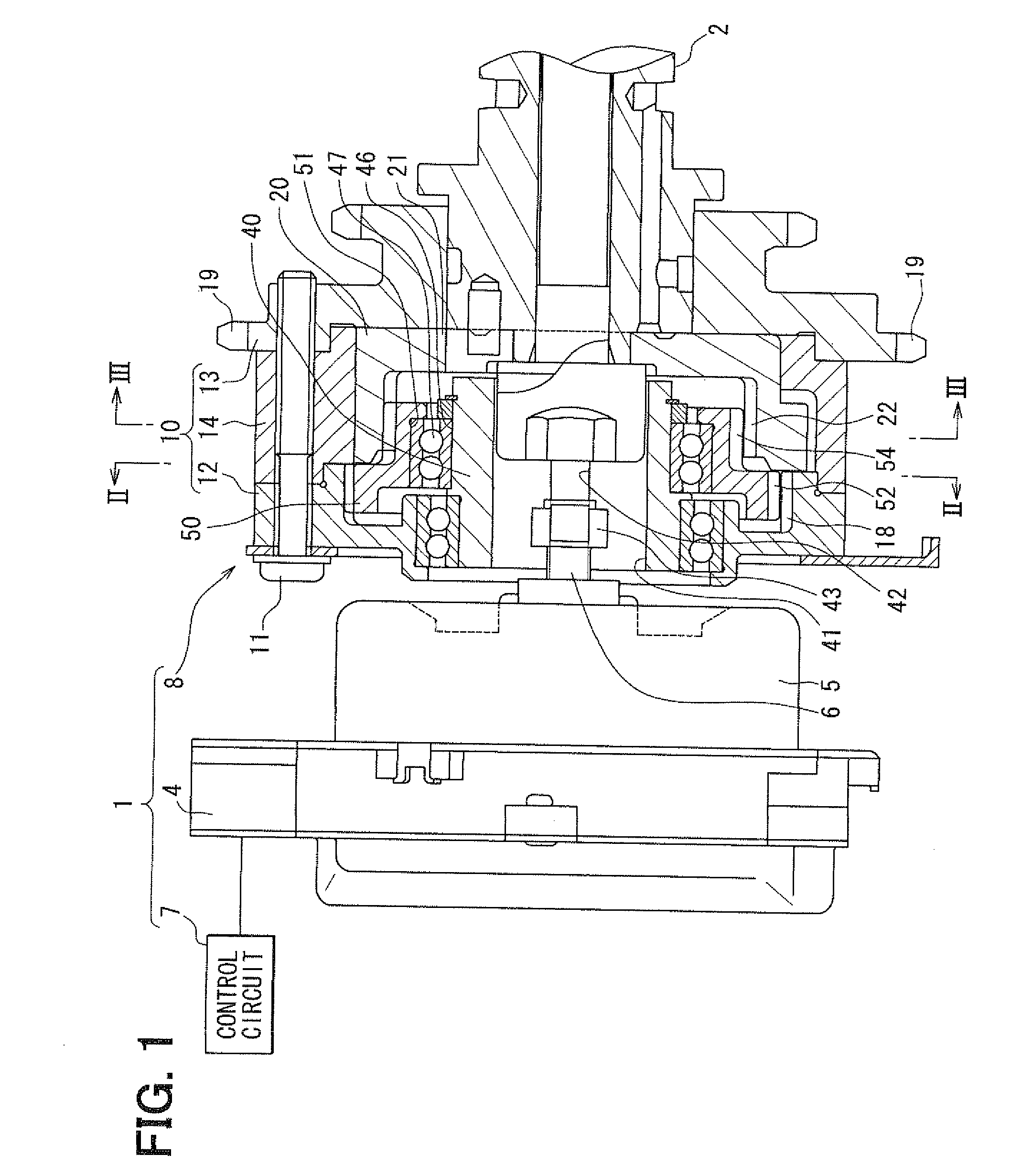
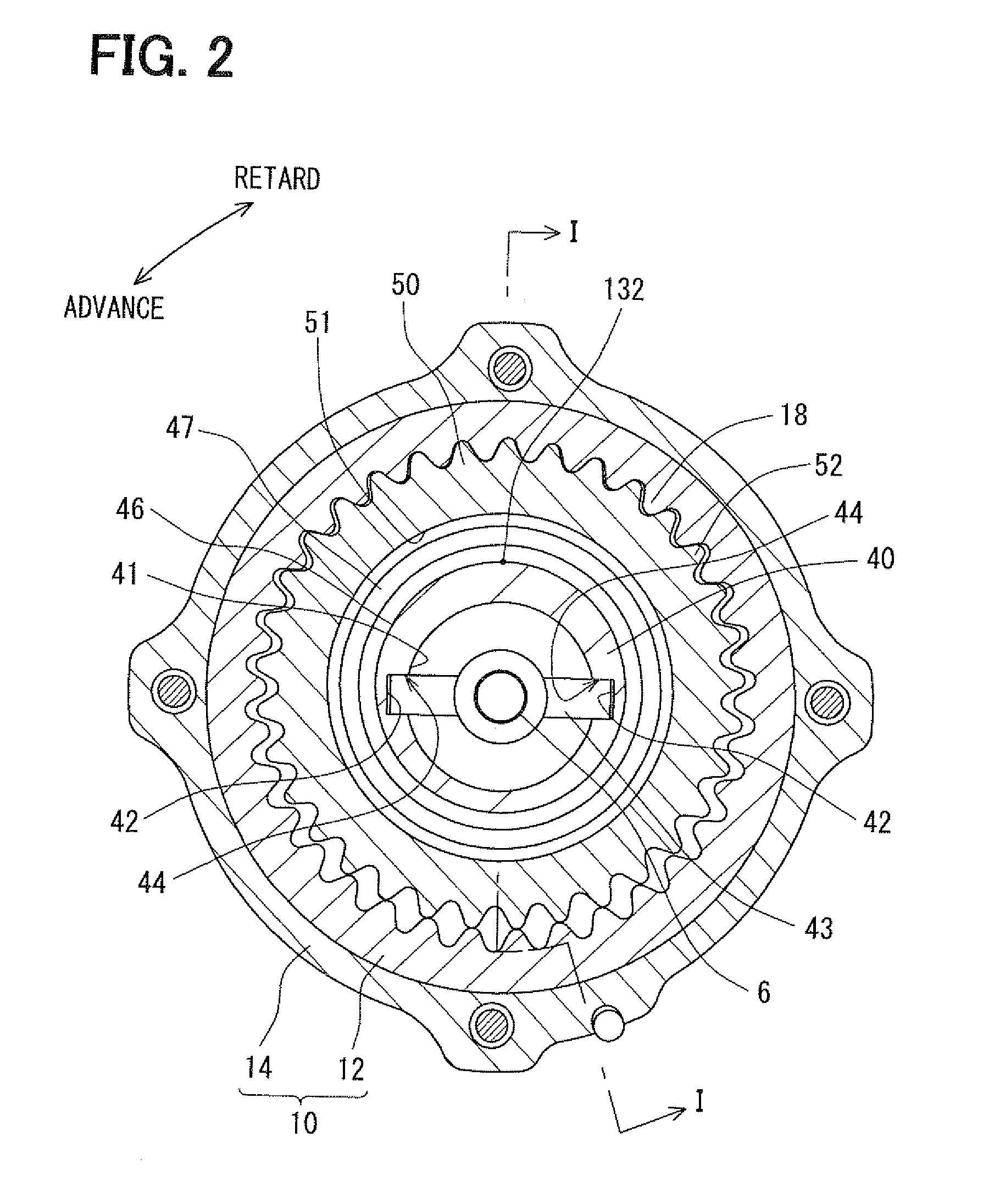
[0040]FIG. 1 shows a valve timing controller 1 according to a first embodiment of the present invention. The valve timing controller 1 is mounted on a vehicle, and more specifically, the valve timing controller 1 is mounted on a transmission system that transmits an engine torque from a crankshaft (not shown) to a camshaft 2 of an internal combustion engine. It should be noted that in the present embodiment the camshaft 2 opens and closes an intake valve (not shown) that serves as a “valve” of the internal combustion engine through transmission of the engine torque. The valve timing controller 1 adjusts a rotational phase between the crankshaft and the camshaft 2 to get a desired valve timing of the intake valve.
(Basic Configuration)
[0041]A basic configuration of the valve timing controller 1 of the first embodiment will be described below. The valve timing controller 1 includes an electric actuator 4, an energizing control circuit unit 7, and a phase adjusting mechanism 8.
[0042]The...
second embodiment
[0068]As shown in FIGS. 7 and 8, a second embodiment is a modification of the first embodiment. In the second and the successive embodiments, the same parts and components as those in the first embodiment are indicated with the same reference numerals and the same descriptions will not be reiterated. An outermost point 2301a of a bottom portion 2301 of the introducing port 230 is located apart from the maximum eccentric point 132 of the supporting outer surface 46 and the periphery surface 100 of the camshaft 2 with respect to the center line “O”. The introducing port 230 has a bottom portion 2301 which is radially outwardly located with respect to the periphery surface 100 of the camshaft 2. Thus, a second side-opening 2303 of the introducing port 230 on the driven-rotor-side-surface 102 radially extends across the supporting interface 104.
[0069]According to such a configuration, the lubricant in the space 1306 is easily introduced into the supporting interface 104 and the sliding ...
third embodiment
[0071]As shown in FIGS. 10 and 11, a third embodiment is a modification of the first embodiment. In the third embodiment, an outermost diameter of the annular groove 320 is larger than a diameter of the periphery surface 100 of the camshaft 2, which defines the supporting interface 104 in cooperation with the sprocket member 13. Also, the outermost radius of the annular groove 320 is larger than a distance between the outermost point 1301a and the center line “O”. Thus, a width of an opening 3200 of the annular groove 320 on the driven-rotor-side-surface 102 radially extends across the supporting interface 104. The stepped surface 122 of the camshaft 2 is in contact with the driven-rotor-side-surface 102 inside of the annular groove 320.
[0072]According to such a configuration, the annular groove 320 crossing the supporting interface 104 directly introduces the lubricant to the supporting interface 104 and the sliding interface 106, as shown in FIG. 12. Thus, the lubricating property...
PUM
 Abstract
Description
Claims
Application Information
 - R&D
- Intellectual Property
- Life Sciences
- Materials
- Tech Scout
- Unparalleled Data Quality
- Higher Quality Content
- 60% Fewer Hallucinations
Browse by: Latest US Patents, China's latest patents, Technical Efficacy Thesaurus, Application Domain, Technology Topic, Popular Technical Reports.
© 2025 PatSnap. All rights reserved.Legal|Privacy policy|Modern Slavery Act Transparency Statement|Sitemap|About US| Contact US: help@patsnap.com


