Starting method of coal gasifier and starting device therefor

a gasifier and starting device technology, applied in the direction of fuel gas production, combustible gas production, electrochemical generators, etc., can solve the problem of difficult restart of furnace operation, and achieve the effect of restrainting the height of the whole furna

Active Publication Date: 2010-07-22
MITSUBISHI POWER LTD
View PDF4 Cites 14 Cited by
  • Summary
  • Abstract
  • Description
  • Claims
  • Application Information

AI Technical Summary

Benefits of technology

[0019]In view of the above-described background, the present invention aims at providing a starting method of a coal gasifier and a starting device thereby, whereby pulverized coal is transferred toward the furnace inside by use of an inert transfer gas and the coal thrown into the furnace inside is burnt so that the coal is gasified, wherein a warm-up (start-up) burner can be dispensed with, and a start-up combustion chamber can be accordingly eliminated; a start-up combustion chamber can be down-sized in comparison with the conventional start-up combustion chambers, even when a start-up chamber has to be provided; and, the height of the whole furnace can be restrained.

Problems solved by technology

Hence, in a case where a starting burner for starting the operation of the furnace is provided at the combustor side of the furnace, the tip part of the starting burner the part which protrudes toward the furnace inside is covered with the slag when the starting burner is stopped and the operation of the furnace is stopped for a long duration of time before the next operation; thus, the restart of the furnace operation becomes difficult; therefore, the starting burner is needed to be, as it used to be, placed at a starting combustion chamber that is provided independently from the combustor.

Method used


Image

  • Starting method of coal gasifier and starting device therefor
  • Starting method of coal gasifier and starting device therefor
  • Starting method of coal gasifier and starting device therefor

Examples


first embodiment

The First Embodiment

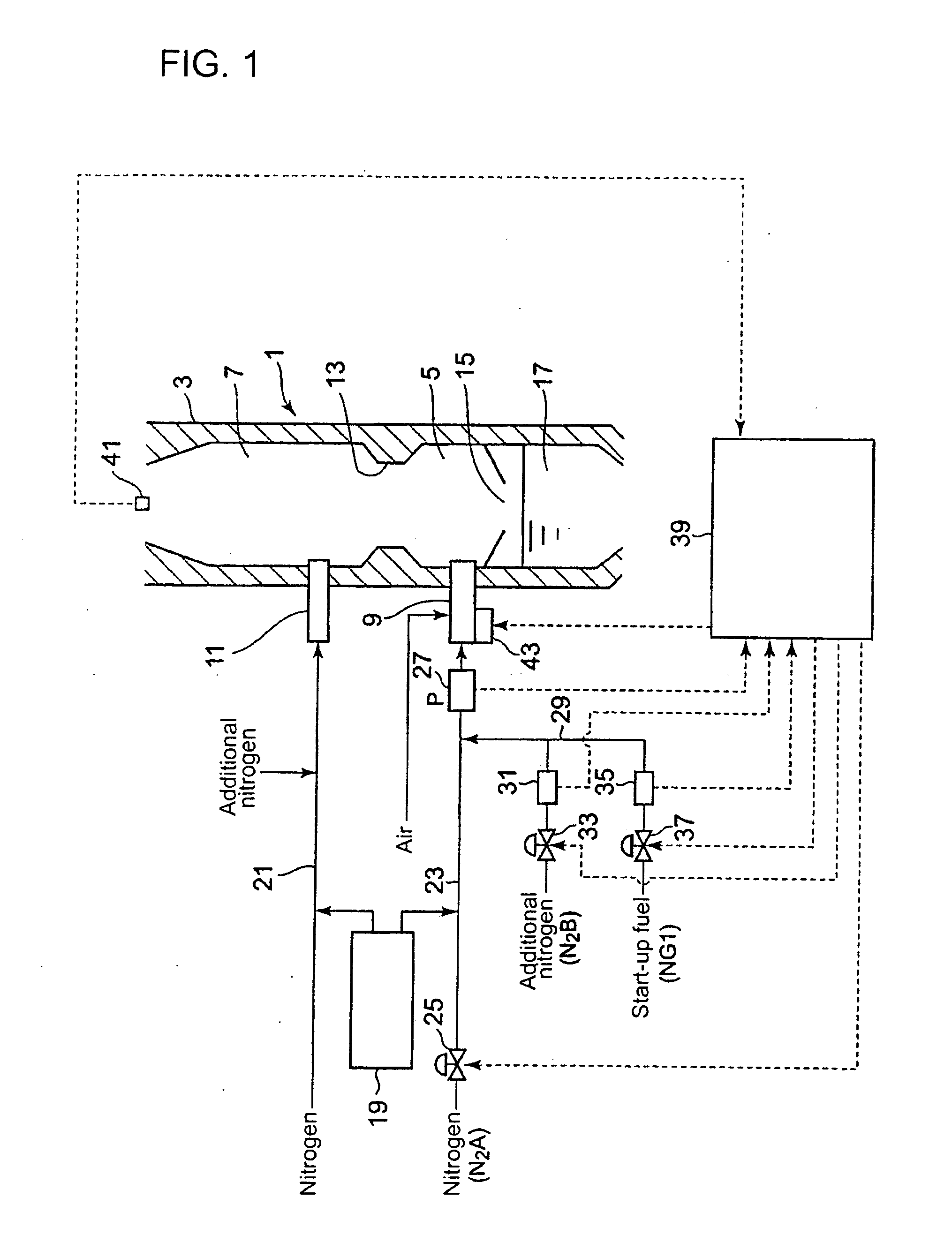
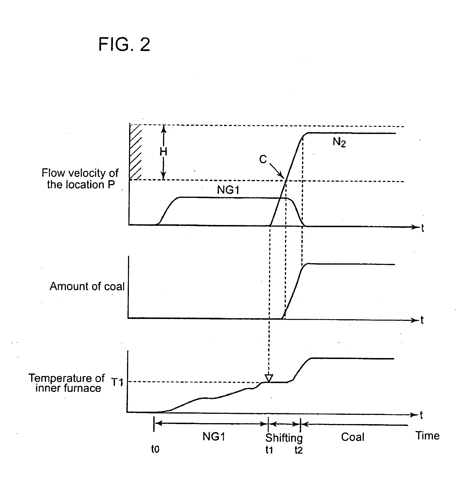
[0052]The first embodiment according to the present invention is now explained in consultation with FIGS. 1 and 2. FIG. 1 shows an outline of a coal gasifier according to the first embodiment of the present invention.

[0053]As shown in FIG. 1, a pressure vessel 3 forms a coal gasifier 1 that gasifies coal, and comprises a combustor (a combustion furnace) 5 which generates heat and a reductor (a reduction furnace) 7 which performs coal gasification reaction by use of the heat generated in the combustor 5. The combustor 5 is provided with at least one combustor burner (a combustion burner) 9 and the reductor 7 is provided with at least one reductor burner 11; in the attached figures, only one combustor burner and only one reductor burner are shown (the other burners are omitted from the figures).

[0054]Between the combustor burner 9 and the reductor burner 11, a partition area (a neck area) 13 is formed; below the combustor burner 9, a slag discharge port, namely sla...

second embodiment

The Second Embodiment

[0071]The second embodiment according to the present invention is now explained in consultation with FIGS. 3 and 4. FIG. 3 shows an outline of a coal gasifier according to the second embodiment of the present invention, whereby FIG. 1 corresponds to the first embodiment, while FIG. 3 corresponds to the second embodiment.

[0072]The difference between the first and second embodiments is that an assist warm-up burner (a start assist burner) 50 is provided in the second embodiment in contrast to the first embodiment. Except this difference, the same configuration as that of the first embodiment is followed; thus, the same symbol is used for a same configuration member.

[0073]As shown in FIG. 3, the assist warm-up burner (a start assist burner) 50 is provided below the combustor burner 9 as well as the slag tap 15; a start control means 52 for controlling the operation of the furnace comprises a start assist burner controller 54 for controlling the start-up operation o...

third embodiment

The Third Embodiment)

[0082]The third embodiment according to the present invention is now explained in consultation with FIG. 5.

[0083]In the method as well as device thereby, according to this third embodiment, a sealing gas supply passage 67 for supplying an inert sealing gas toward the (coal) fuel supply passage 23 is provided, the supply passage 67 being connected to a point on the passage 23 between the (coal hopper) outlet 63 of a pulverized coal hopper (funnel) 19 for storing and supplying the pulverized coal and a junction point (a cross point) 65 as to the passage 23 and the starting gas supply passage 29.

[0084]In the sealing gas supply passage 67, nitrogen gas as a sealing gas is supplied.

[0085]By supplying the sealing gas as described above, the starting flammable gas for starting-up the operation of the furnace can be prevented from flowing back in the (coal) fuel supply passage 23 toward the pulverized coal hopper (funnel) 19. Thus, the starting flammable gas can be stab...


PUM

PropertyMeasurementUnit
flammableaaaaaaaaaa
temperatureaaaaaaaaaa
flow rateaaaaaaaaaa

Abstract

In a coal gasification furnace adapted to feed pulverized coal thereinto by the use of inert carrier gas and gasify the same, any startup burner can be unnecessitated thereby eliminating any startup combustion chamber. Further, even in the use of a startup burner, it is smaller and lighter in weight than conventional startup burners, allowing the startup combustion chamber to be compact and limiting the height of the entirety of the gasification furnace. As a characteristic feature, a pulverized coal fuel supply passageway (23) to a combustor burner (9) is provided at its midstream portion with a startup gas supply passageway (29) for supply of a startup combustible gas (NG1). After reaching of the temperature of the furnace interior to a first temperature (T1) allowing ignition of pulverized coal with reference to a detected value from furnace interior temperature detecting means (41), transition to combustion by the pulverized coal and carrier gas is effected by increasing the input rate of pulverized coal and carrier gas while decreasing the supply rate of combustible gas (NG1) from the startup gas supply passageway (29).

Description

BACKGROUND OF THE INVENTION[0001]1. Field of the Invention[0002]The present invention relates to a starting method and a device therefor for starting the operation of a coal gasifier in which pulverized coal is charged into the furnace by means of inert transfer-gas (carrier-gas); more in detail, the invention relates to a starting method preferred for starting the operation of the coal gasifier by means of flammable gas, and a device for enforcing the starting method.[0003]2. Background of the Invention[0004]In a coal gasifier of a pressurized two-stage entrained-bed type and an air blowing type the furnace which includes a combustor and a reductor; the ash content in the coal as fuel is melted; vitreous slag is formed in the furnace and discharged therefrom; thus, the inner wall of the furnace in operation is covered with the melted slag. Hence, in a case where a starting burner for starting the operation of the furnace is provided at the combustor side of the furnace, the tip par...

Claims


Application Information

Patent Timeline
Patent Type & Authority Applications(United States)
IPC IPC(8): C10J3/68C10J3/00C10J1/207
CPCC10J3/466C10J2300/093C10J3/726
Inventor YOKOHAMA, KATSUHIKOISHII, HIROMIKITAGAWA, YUICHIRO
Owner MITSUBISHI POWER LTD
Why Eureka
Try Eureka