
Methods and systems for calibrating vehicle vision systems

a technology for vehicle vision and system calibration, applied in the field of vehicles, can solve the problems of difficult calibration of vehicle vision systems and difficulty in properly recognizing, and achieve the effects of facilitating pattern projecting, facilitating pattern projecting, and facilitating calibration of vision systems

Inactive Publication Date: 2010-07-15
GM GLOBAL TECH OPERATIONS LLC
View PDF2 Cites 28 Cited by
  • Summary
  • Abstract
  • Description
  • Claims
  • Application Information

AI Technical Summary

Benefits of technology

[0005]In accordance with another exemplary embodiment of the present invention, a program product for calibrating a vision system of a vehicle is provided. The program product comprises a program and a computer-readable signal-bearing media. The program is configured to at least facilitate projecting a pattern in proximity to the vehicle and calibrating the vision system using an image of the pattern generated by the vision system. The computer-readable signal-bearing media bears the program.
[0006]In accordance with a further exemplary embodiment of the present invention, a system for calibrating a vision system of a vehicle is provided. The system comprises a projection unit and a processor. The projection unit is configured to at least facilitate projecting a pattern in proximity to the vehicle. The processor is configured to at least facilitate calibrating the vision system using an image of the pattern generated by the vision system.

Problems solved by technology

However, it can be difficult to properly recognize the various different visible reference points that may surround the vehicle at any particular point in time, thus making calibration of the vehicle vision systems more difficult.

Method used


Image

  • Methods and systems for calibrating vehicle vision systems
  • Methods and systems for calibrating vehicle vision systems
  • Methods and systems for calibrating vehicle vision systems

Examples


Embodiment Construction

[0010]The following detailed description is merely exemplary in nature, and is not intended to limit the invention or the application and uses of the invention. Furthermore, there is no intention to be bound by any expressed or implied theory presented in the preceding technical field, background, brief summary or the following detailed description.

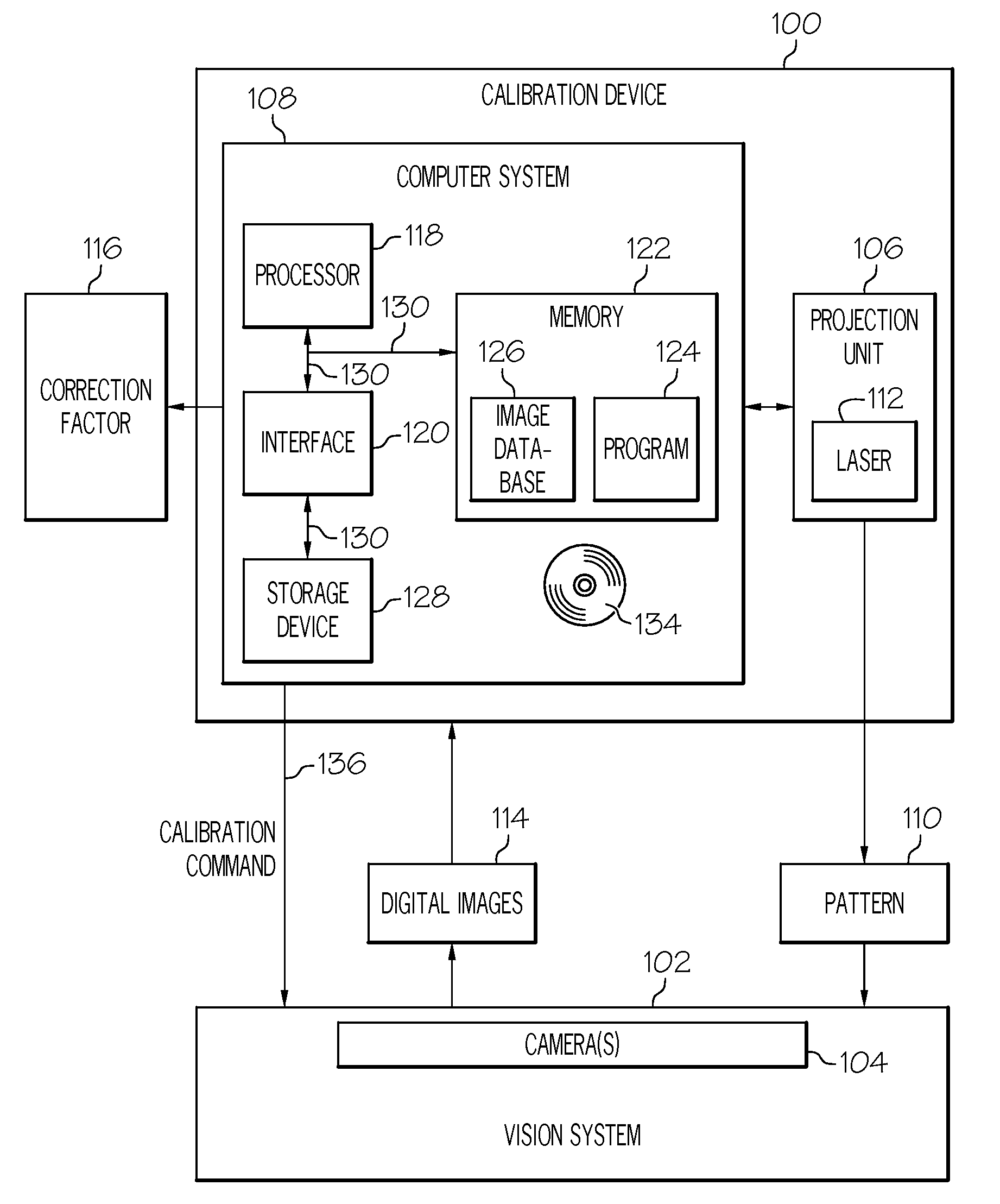
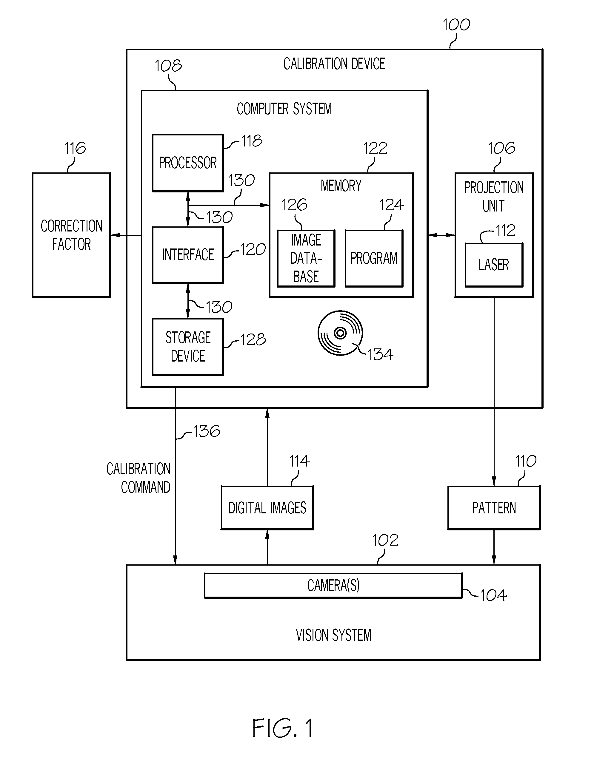
[0011]FIG. 1 is a functional block diagram of a calibration device 100 for calibrating a vision system 102 of a vehicle, in accordance with an exemplary embodiment of the present invention. As depicted in FIG. 1, the vision system 102 being calibrated has one or more cameras 104. In various embodiments, the cameras 104 may include any one or more of a number of devices that generate and / or record still images and / or moving images. The vision system 102 may include, by way of example only, one or more of the following: a rear view camera, a collision alert system, a lane departure warning system, an adaptive cruise control system, a high b...


PUM


Abstract

A method for calibrating a vision system of a vehicle includes the steps of projecting a pattern in proximity to the vehicle and calibrating the vision system using an image of the pattern generated by the vision system.

Description

TECHNICAL FIELD[0001]The present invention generally relates to the field of vehicles and, more specifically, to methods and systems for calibrating vision systems of vehicles.BACKGROUND OF THE INVENTION[0002]Certain vehicles today utilize cameras in various vehicle vision systems including, for example rear view cameras, collision alert systems, lane departure warning systems, adaptive cruise control systems, high beam assist systems, pedestrian recognition systems, and traffic sign recognition systems. These vehicle vision systems may be calibrated from time to time to help ensure that the associated cameras are aligned properly and provide optimal images. Typically, such calibration is performed by using visible reference points, such as buildings, bridges, or the horizon. However, it can be difficult to properly recognize the various different visible reference points that may surround the vehicle at any particular point in time, thus making calibration of the vehicle vision sys...

Claims


Application Information

Patent Timeline
Patent Type & Authority Applications(United States)
IPC IPC(8): G01P21/00G06V10/147
CPCB60R11/04G06K9/00791H04N17/002G06T7/0018G06K9/209G06T7/80G06V20/56G06V10/147
Inventor RAPHAEL, ERIC L.
Owner GM GLOBAL TECH OPERATIONS LLC
Learn More